Directional Backlight with Reduced Crosstalk

Inactive Publication Date: 2011-11-24
3M INNOVATIVE PROPERTIES CO
View PDF5 Cites 118 Cited by
  • Summary
  • Abstract
  • Description
  • Claims
  • Application Information

AI Technical Summary

Benefits of technology

[0005]We have developed a class of backlights suitable for use in autostereoscopic displays, although they can also be used in other (non-autostereoscopic) display and/or lighting applications. These backlights can provid

Problems solved by technology

Further, if the left and right sources provide alternating illumination for a directional backlight structure which extracts light based on the light source end when the right eye image light input surface opposes a left eye image light input surface, light entering either surface ca

Method used


Image

  • Directional Backlight with Reduced Crosstalk
  • Directional Backlight with Reduced Crosstalk
  • Directional Backlight with Reduced Crosstalk

Examples


Embodiment Construction

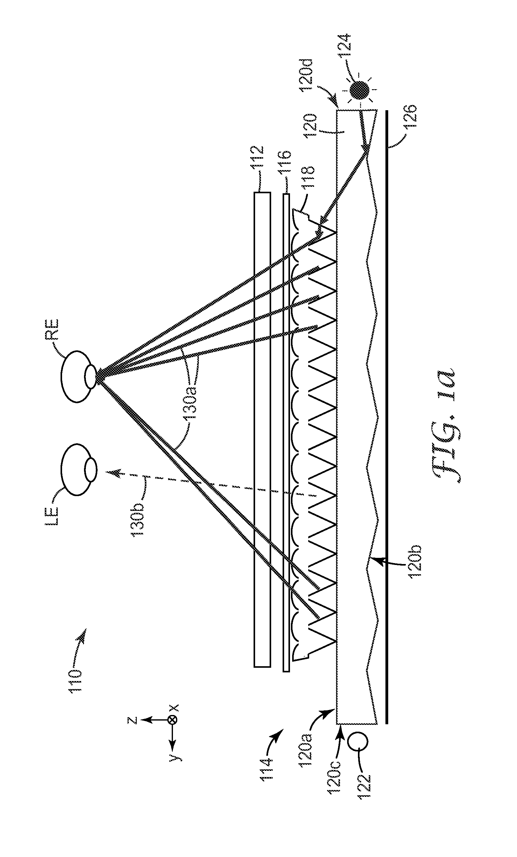
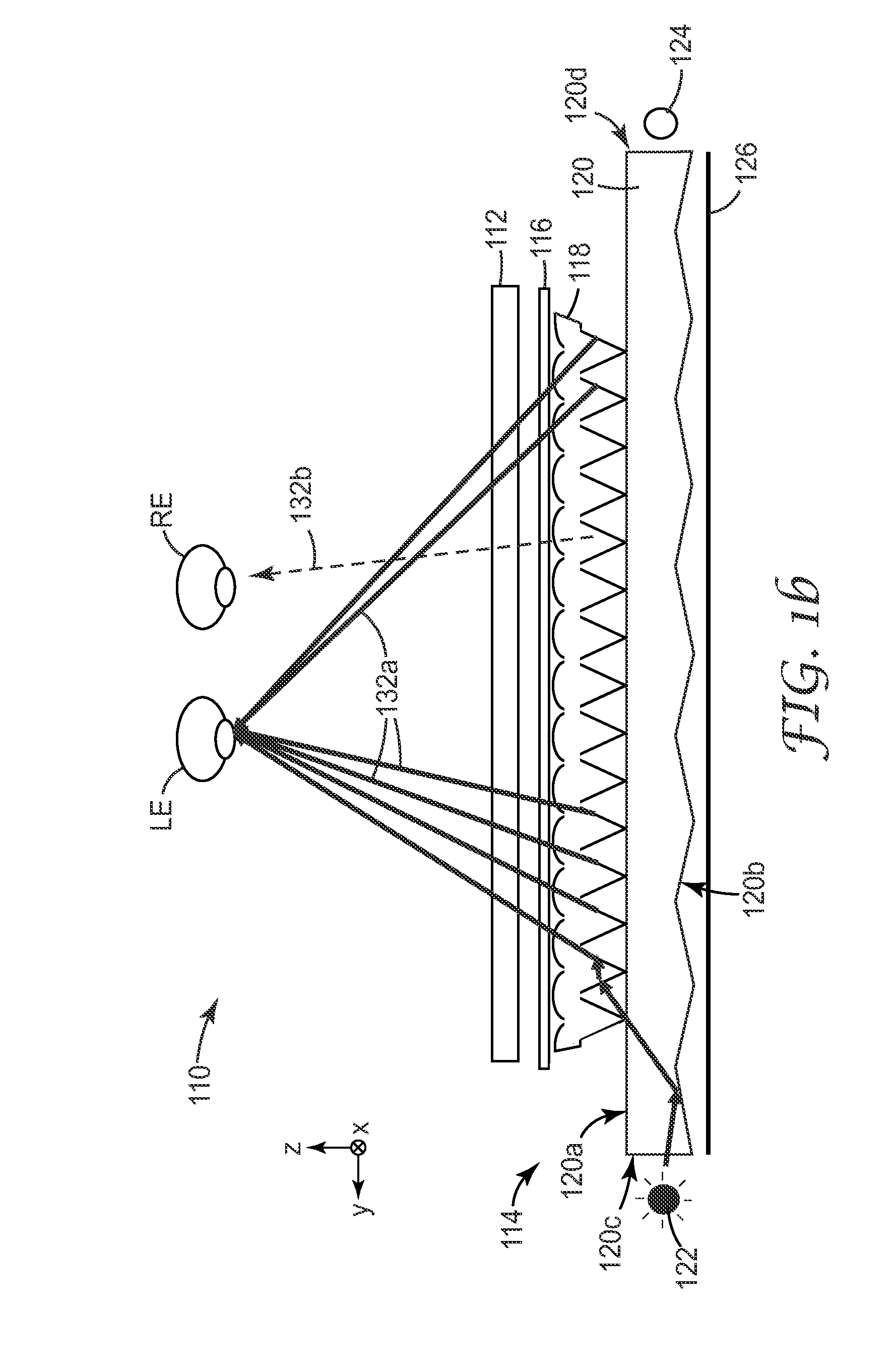
[0030]As outlined above, we describe herein, among other things, techniques that reduce light reflection from the far end of a light guide—i.e., the end of the light guide farthest from the light source assembly being energized—in a backlight suitable for use in an autostereoscopic display. The techniques can reduce visual crosstalk between left and right images, resulting in an improved autostereoscopic 3D viewing experience.

[0031]In some cases, the techniques utilize only a simple flat surface for each end of the light guide, and also use material(s) that strongly absorb visible light and that are spaced apart from, but typically in relatively close proximity to, the light guide in order to reduce or minimize the amount of light reflected back into the light guide, thus reducing crosstalk. The absorptive material, which typically would have a black appearance due to strong absorption over at least visible wavelengths, may be applied e.g. in a thin or thick film to surfaces of exis...


PUM


Abstract

A backlight suitable for use in an autostereoscopic display includes a light guide and a first and second light source assembly. The light guide has opposed first and second major surfaces, and opposed first and second side surfaces. The first and second light source assemblies are disposed to inject visible light into the light guide through the first and second side surfaces, respectively. Substantially all of the first side surface highly transmits a second light portion out of the light guide into air, the second light portion originating from the second light source assembly, and substantially all of the second side surface highly transmits a first light portion in a corresponding fashion. One or more first non-emitting surfaces of the first light source assembly are disposed at least partially between two light-emitting surfaces of the first light source assembly, and are adapted to substantially absorb visible light to reduce crosstalk.

Description

FIELD OF THE INVENTION[0001]This invention relates generally to backlit displays, with particular application to such displays that present distinct left- and right-eye images to allow for stereoscopic viewing, and backlights therefor. The invention also relates to associated articles, systems, and methods.BACKGROUND[0002]A stereoscopic display usually presents an observer with images with parallax from individual right and left eye viewpoints. There are several techniques of providing the two eyes of the observer with the parallax images. In a first common stereoscopic technique, the observer utilizes a pair of shutter or 3D glasses which transmit or block light from the viewer's eyes in synchronization with alternating the left / right image display. In a second technique, right eye and left eye images are alternatively displayed and directed towards the respective eyes of the observer but without the use of 3D glasses. This second technique is referred to as autostereoscopic, and i...

Claims


Application Information

Patent Timeline
IPC IPC(8): G02F1/1335H01J9/24F21V7/22
CPCH04N13/0418H04N13/32G02B6/10G02F1/1335
Inventor SCHULTZ, JOHN C.SYKORA, MICHAEL J.
Owner 3M INNOVATIVE PROPERTIES CO
Why Eureka
Try Eureka