Origin position signal detector

a position signal and detector technology, applied in the direction of magnetic measurements, instruments, measurement devices, etc., can solve the problems of increasing or decreasing the height of the side peak, the inability to set the designed threshold voltage extremely low, and the inability to detect the origin position detection signal accurately, so as to improve the stability reduce the false detection of the origin position detection signal, and improve the effect of stability

Inactive Publication Date: 2011-12-01
MITSUBISHI ELECTRIC CORP
View PDF5 Cites 23 Cited by
  • Summary
  • Abstract
  • Description
  • Claims
  • Application Information

AI Technical Summary

Benefits of technology

[0020]According to the origin position signal detector of the one aspect of the present invention, providing the side magnetized portions on both sides of the origin position magnetized portion allows the origin position detection track to lower the output value of the side peak that is associated with the analog signal outputted from the magnetic sensor. Thus, a threshold voltage for generating an origin position detection signal can be set lower. As a result, it is possible to improve stability in detection of the origin position detection signal when the temperature is high, as well as to reduce false detection of the origin position detection signal due to the side peak exceeding the preset threshold voltage when the temperature is low. Consequently, according to the origin position signal detector of the one aspect of the present invention, it is possible to detect the origin position detection signal in the magnetic encoder with greater stability as compared to the conventional example.

Problems solved by technology

In addition, the origin position detection signal increases or decreases due to factors such as an assembly error of the magnetism detecting sensor with respect to the rotary drum.
There are also variations of the height in the side peak due to the setting error of the threshold voltage and the assembly error of the magnetism detecting sensor as described above.
Consequently, it is practically impossible to set the designed threshold voltage to be extremely low.
Therefore, when the output in the side peak exceeds the threshold voltage that has been set, the origin position signal detector possibly detects the side peak, resulting in false detection of the origin position.

Method used


Image

  • Origin position signal detector
  • Origin position signal detector
  • Origin position signal detector

Examples


embodiment 1

[0056]The following describes an origin position signal detector according to an embodiment 1 of the present invention with reference to FIG. 1 to FIG. 5.

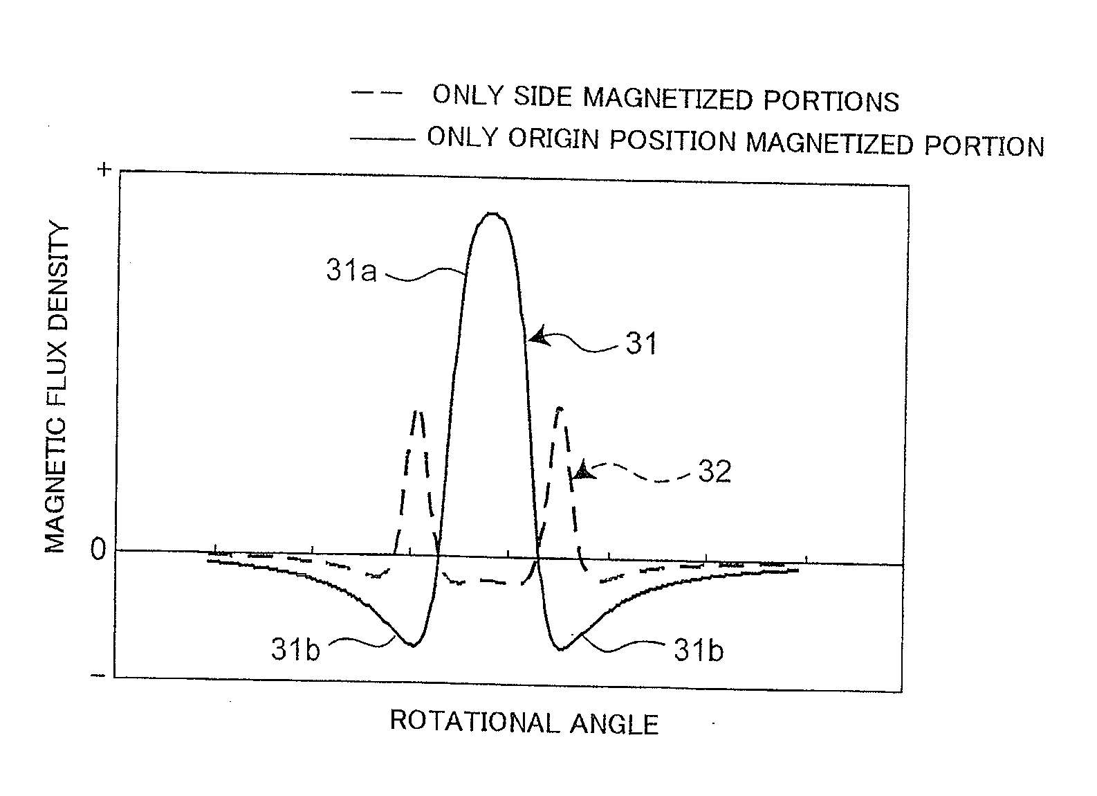
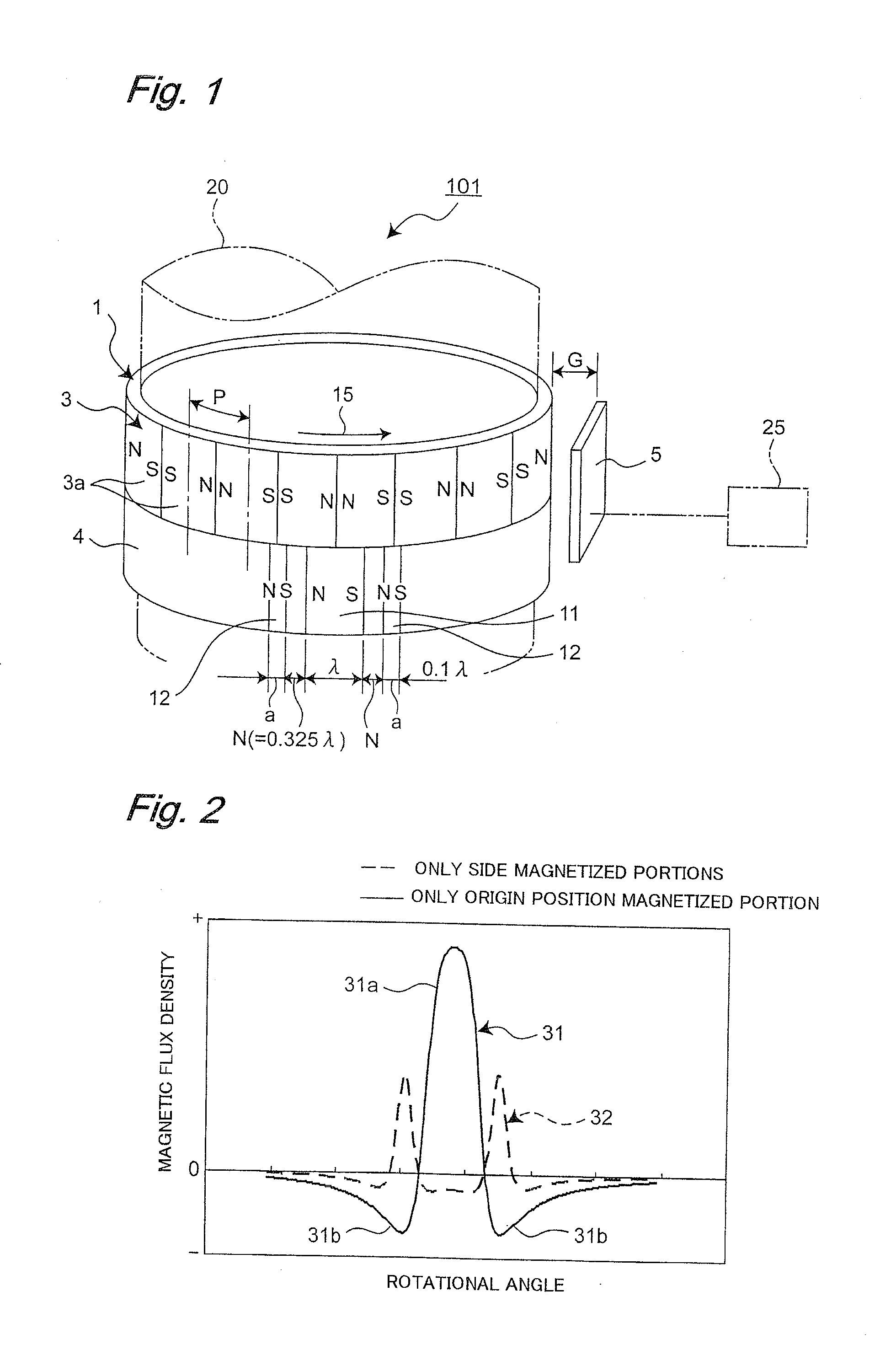
[0057]FIG. 1 shows a schematic configuration of an origin position signal detector 101 according to this embodiment, the detector serving as a magnetic rotational angle sensor among magnetic rotary encoders. The origin position signal detector 101 roughly has a detection target member 1 and a magnetoresistance element 5 as an example that serves a function of a magnetic sensor.

[0058]The detection target member 1 is a magnet that is attached along an outer circumferential surface of a rotary drum 20 that corresponds to a rotary shaft of a motor and the like, for example, by means of application, fitting, adhesion, and such. In the detection target member 1, an incremental track 3 and an origin position detection track 4 are arranged in a two-tiered manner in an axial direction of the rotary drum 20.

[0059]In order to detect a displac...

embodiment 2

[0074]An embodiment 2 according to the present invention will be now described with reference to FIG. 6 to FIG. 8.

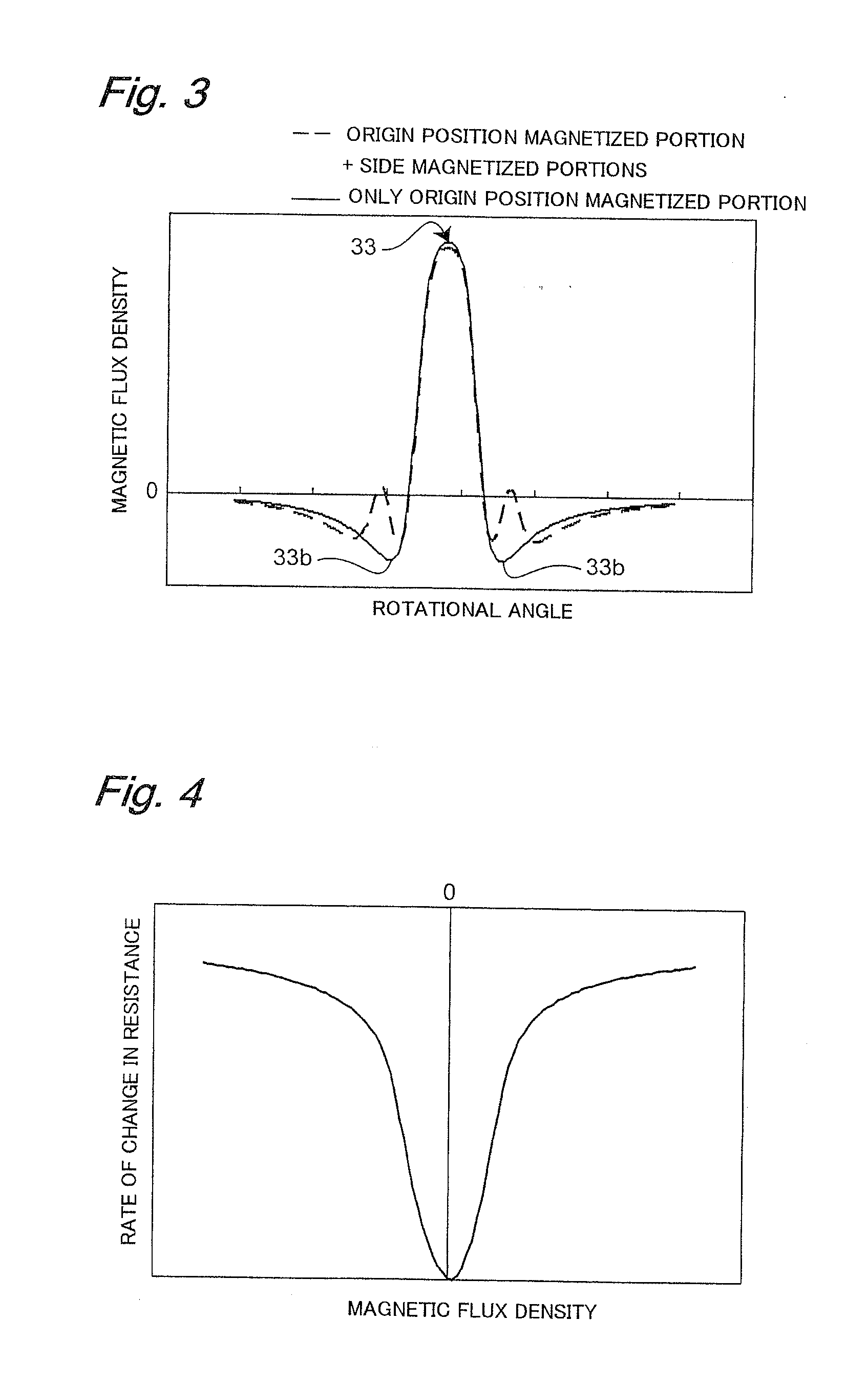
[0075]Here, FIG. 6 shows a schematic configuration of an origin position signal detector 102 according to the embodiment 2 of the present invention. FIG. 7 shows, by comparison, the results of the simulation of the time change in distribution of magnetic flux density of the magnetoresistance element in the origin position signal detector 101 according to the embodiment 1, and results of simulation of a time change in distribution of magnetic flux density of a magnetoresistance element in the origin position signal detector 102 according to the embodiment 2. It should be noted that, in FIG. 7, a solid line represents the case of the origin position signal detector 101, and a dotted line represents the case of the origin position signal detector 102. FIG. 8 shows a chart converted to a rate of change in resistance of the AMR element due to the rotation of the rotary drum i...

embodiment 3

[0092]An embodiment 3 according to the present invention will be now described with reference to FIG. 9.

[0093]An origin position signal detector 103 according to the embodiment 3 is configured such that the configuration of the origin position track according to the embodiment 1 is applied to the magnetic position detection sensor.

[0094]FIG. 9 shows a schematic configuration of the origin position signal detector 103 according to this embodiment, the detector serving as a magnetic positional sensor among magnetic linear encoders. The origin position signal detector 103 roughly comprises a detection target member 52 and a magnetoresistance element 55. The detection target member 52 is a plate-like magnet which is attached onto a linear scale plate 51 for example, by means of application, adhesion, and such. Along the detection target member 52, an incremental track 53 and an origin position detection track 54 are provided in a two-tiered manner, and the tracks 53 and 54 extend along ...


PUM


Abstract

An origin position signal detector comprising: a rotary or linear scale (1) which includes an incremental track (3) magnetized at equal intervals and an origin position detection track (4) for detecting an origin position, and a magnetic sensor (5) which detects magnetic fields from the scale. The origin position detection track includes an origin position magnetized portion (11) and side magnetized portions (12) provided on both sides of the origin position magnetized portion (11) and magnetized with magnetization in the same direction at one or more positions as the origin position magnetized portion (11).

Description

TECHNICAL FIELD[0001]The present invention relates to an origin position signal detector capable of detecting an origin position in magnetic rotational angle sensors such as magnetic rotary encoders and magnetic position detectors such as magnetic linear encoders.BACKGROUND ART[0002]A magnetic rotational angle sensor is known as an example in which a typical origin position signal detector is used. This magnetic rotational angle sensor is roughly provided with a rotary drum that is mounted to a rotary shaft of a motor and such, for example, and changes the generated magnetic field according to its rotation, and a magnetism detecting sensor that detects the varying magnetic field (Patent Document 1, for example).[0003]Magnets are provided along an outer circumferential surface of the rotary drum by such as application, fitting, and adhesion. Its detection tracks include an incremental track for detecting a rotational angle of the rotary drum and an origin position detection track for...

Claims


Application Information

Patent Timeline
Patent Type & Authority Applications(United States)
IPC IPC(8): G01R33/00
CPCG01D5/2457
Inventor MUSHA, TAKESHINISHIZAWA, HIROSHINAKAJIMA, HAJIMEOMURA, YOICHITAKAMUNE, KOICHITAKAMUNE, NORIO
Owner MITSUBISHI ELECTRIC CORP
Why Eureka
Try Eureka