Printhead cartridge for releasable mounting in a printer

a printing cartridge and printer technology, applied in printing, other printing apparatus, etc., can solve the problems of reducing the exertion required to establish the seal fluid coupling, and affecting the efficiency of printing

Active Publication Date: 2011-12-29
MEMJET TECH LTD
View PDF1 Cites 1 Cited by
  • Summary
  • Abstract
  • Description
  • Claims
  • Application Information

AI Technical Summary

Benefits of technology

[0016]Preferably, the fluid flow paths are partially defined by a polymer channel molding having an arrangement of channels and a flexible polymer film sealed over the channels to seal the fluid flow paths from each other, the shut off valves being sealed within the polymer channel molding by the flexible polymer film and the actuator configured to act on an external surface of the flexible polymer film at areas adjacent the shut off valves. Heat sealing a polymer film to a plastic molding is an exceptionally cheap and effective means of providing the sealed flow paths within a fluid manifold. The flexible film allows the actuator to push on the individual shut off valves while remaining sealed from the ink. Accordingly, the actuator can be metal for strength, without the potential problems associated with direct ink contact discussed above. Preferably, the flexible sealing film is polypropylene film foil.

Problems solved by technology

The high print speeds require a large ink supply flow rate.
Not only are the flow rates higher but distributing the ink along the entire length of a pagewidth printhead is more complex than feeding ink to a relatively small reciprocating printhead.
This recognizes that individual ink ejection nozzles may fail over time and eventually there are enough dead nozzles to cause artifacts in the printed image.
The supply flowrate to the pagewidth printhead is too high for needle valves because of the narrow internal diameter.
This requires the coupling conduits to be relatively large and therefore residual ink leaks freely out of the conduits once decoupled from the supply.
In pagewidth printhead cartridges, the leakage problem is exacerbated by the length of the ink flow paths.
Unfortunately, these are unsuitable for the specific requirements of a consumable component such as an ink jet cartridge.
Reaction between the ink and metal can create artifacts in the print.
Secondly, coupling the cartridge to the printer involves relatively high tolerances so that installation is fast and simple.

Method used


Image

  • Printhead cartridge for releasable mounting in a printer
  • Printhead cartridge for releasable mounting in a printer
  • Printhead cartridge for releasable mounting in a printer

Examples


Embodiment Construction

[0053]The invention will be described with specific reference to a fluid coupling between an inkjet print engine and its corresponding printhead cartridge. However, the ordinary worker will appreciate that the invention is equally applicable to other arrangements requiring a detachable fluid connection.

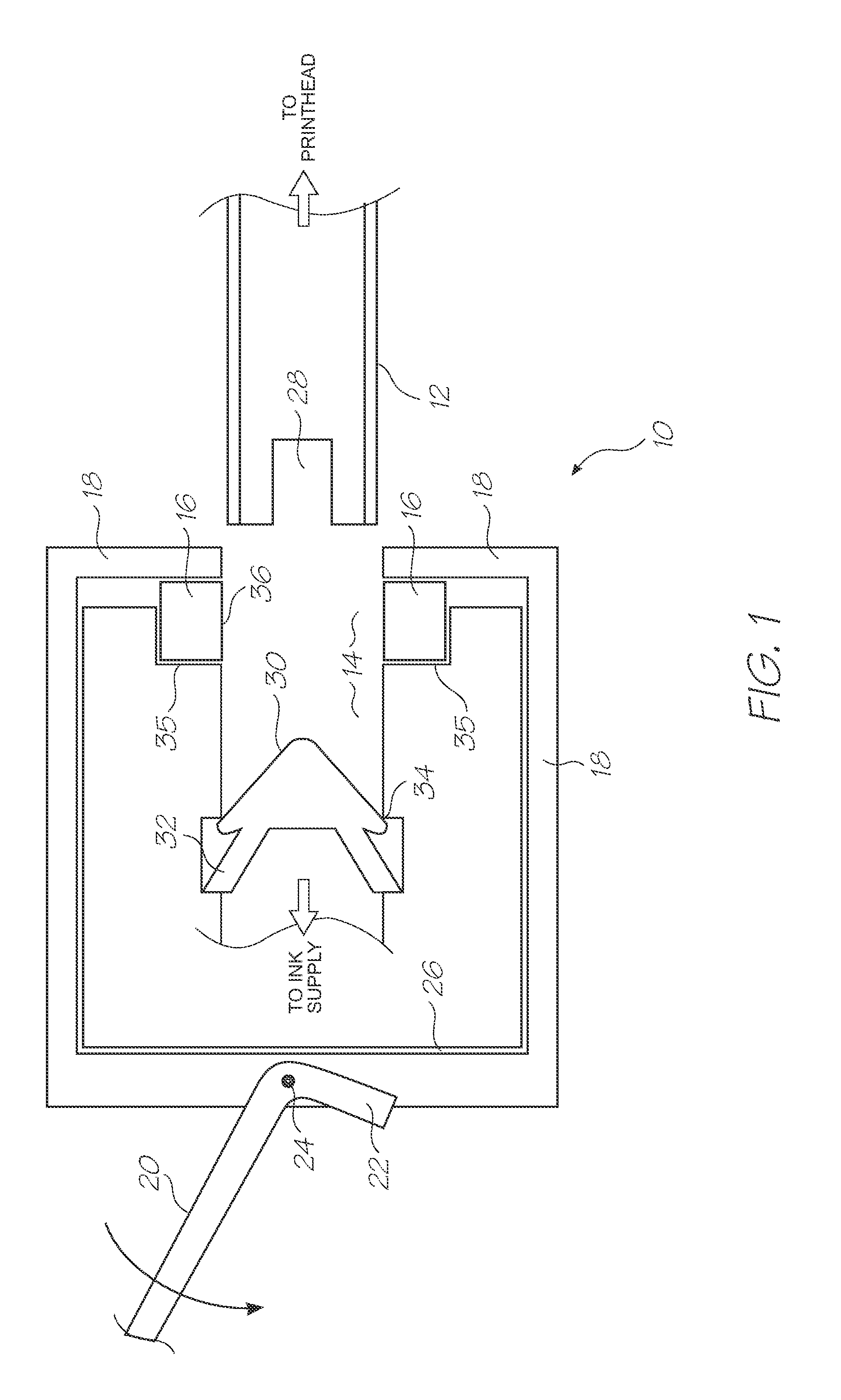
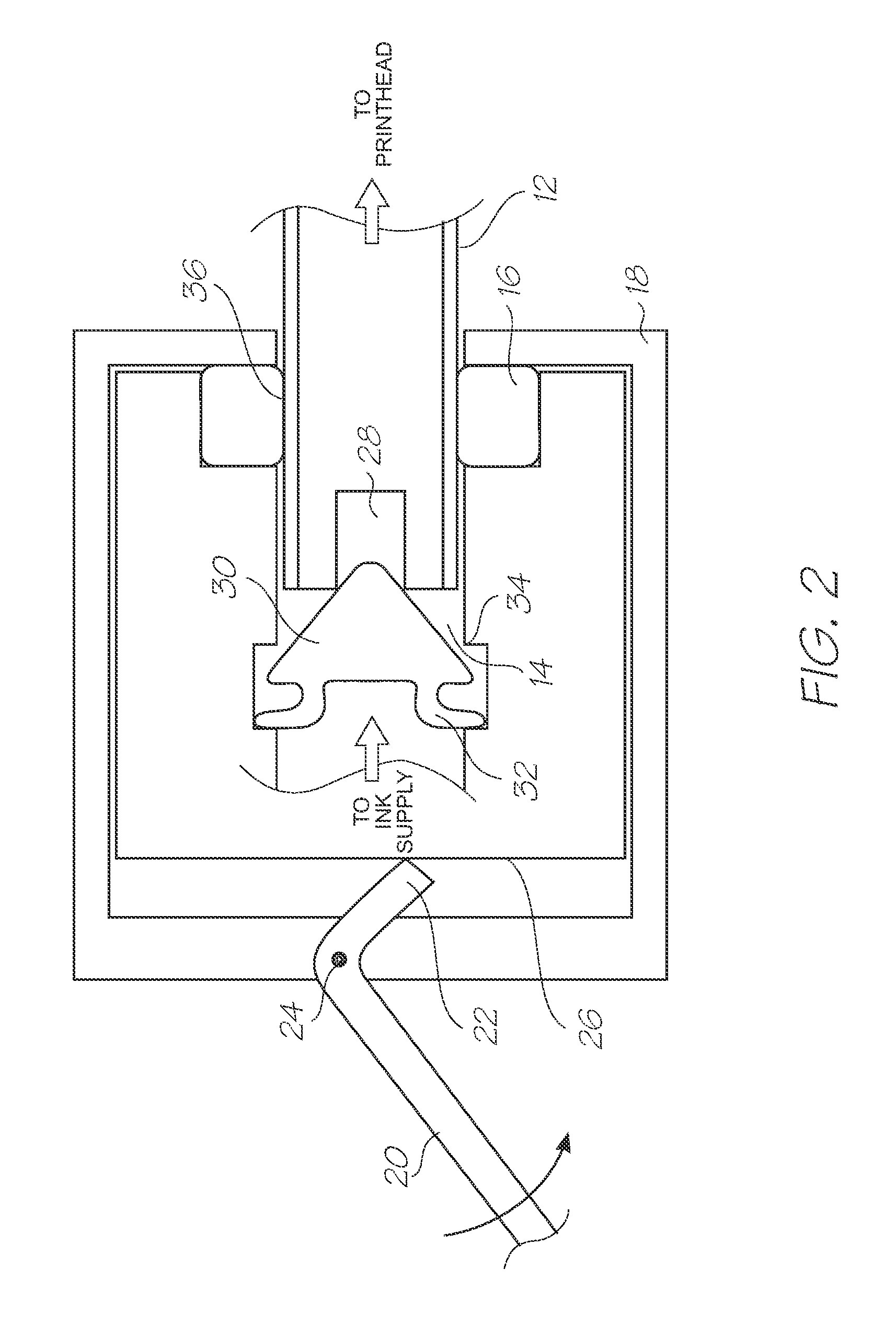
[0054]In FIG. 1, the fluid coupling 10 is shown with the first conduit 12 disengaged from the second conduit 14. The first conduit 12 leads to the pagewidth printhead of the removable printhead cartridge (described below). The second conduit 14 is connected to the ink supply (not shown) and sized such that it can telescopically engage the first conduit 12 with a sliding fit. The ink is retained by the shut off valve 30 biased against valve seat 34 by the resilient struts 32. The second conduit 14 defines a seal seat 35 for the annular seal 16. The annular seal 16 is retained in the seal seat 35 by the compression member 18. In the disengaged position shown in FIG. 1, the annular seal ...


PUM


Abstract

A printhead cartridge for releasable mounting in a printer. The printhead cartridge includes a pagewidth printhead and an ink manifold defining multiple fluid flow paths in fluid communication with respective ink channels in the printhead. The ink manifold includes a plurality of openings for detachable connection with conduits in an interface of the printer; a plurality of shut off valves at each of the openings respectively, each shut off valve having a biasing member configured for biasing each shut off valve into an open position; an actuator biased towards a closed position by a resilient element such that the actuator holds all the shut off valves closed when in the closed position. The actuator is configured for engagement with the interface such that movement of the openings into connection with the interface simultaneously moves the actuator to an open position wherein the shut off valves are held open.

Description

CROSS REFERENCE TO RELATED APPLICATIONS[0001]This application is a Continuation of U.S. application Ser. No. 12 / 339,039 filed on Dec. 19, 2008, the entire contents of which are herein incorporated by reference.FIELD OF THE INVENTION[0002]The present invention relates to fluidic couplings and in particular, ink couplings within inkjet printers.CROSS REFERENCES[0003]The following patents or patent applications filed by the applicant or assignee of the present invention are hereby incorporated by cross-reference.7,744,1957,654,6407,862,1627,758,1497,645,0347,637,6027,645,0337,661,8037,841,7087,771,02911 / 677,0507,658,4827,914,13211 / 872,71812 / 046,44961 / 033,35712 / 062,5147,931,36012 / 062,5187,819,5157,891,79412 / 062,5227,891,78812 / 062,5247,878,63512 / 062,5267,874,6627,984,9817,878,6397,891,7957,878,6408,007,0687,883,18912 / 192,1187,931,3597,887,1487,887,170BACKGROUND OF THE INVENTION[0004]The Applicant has developed a wide range of printers that employ pagewidth printheads instead of tradition...

Claims


Application Information

Patent Timeline
Patent Type & Authority Applications(United States)
IPC IPC(8): B41J2/175
CPCB41J2/1721B41J29/02B41J2/1752B41J2/175
Inventor BERRY, NORMAN MICHEALNAKAZAWA, AKIRASILVERBROOK, KIA
Owner MEMJET TECH LTD
Why Eureka
Try Eureka