Server rack assembly

a server rack and assembly technology, applied in the field of server rack assembly, can solve problems such as inconvenient requirements

Inactive Publication Date: 2012-01-19
HON HAI PRECISION IND CO LTD
View PDF50 Cites 26 Cited by
  • Summary
  • Abstract
  • Description
  • Claims
  • Application Information

AI Technical Summary

Problems solved by technology

When the first pole is to be secured to the second pole and the support, a connecting component mu...

Method used


Image

  • Server rack assembly
  • Server rack assembly
  • Server rack assembly

Examples


Embodiment Construction

[0012]The disclosure is illustrated by way of example and not by way of limitation in the figures of the accompanying drawings in which like references indicate similar elements. It should be noted that references to “an” or “one” embodiment in this disclosure are not necessarily to the same embodiment, and such references mean at least one.

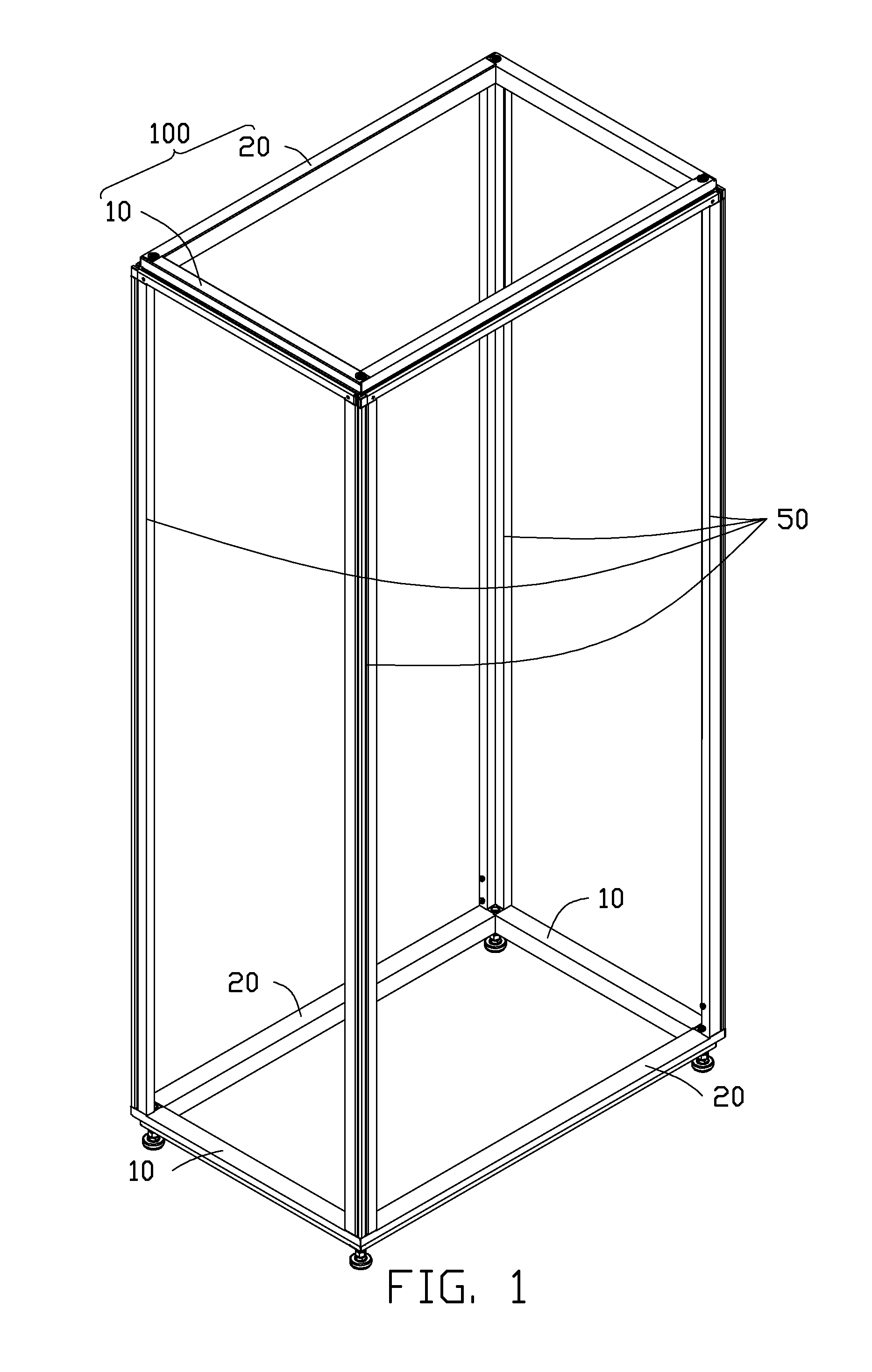
[0013]Referring to FIG. 1, a server rack assembly in accordance with an embodiment includes two frames 100 and four supports 50 located between the two frames 100.

[0014]Each frame 100 includes two first poles 10 parallel to each other, and two second poles 20 parallel to each other. In one embodiment, each frame 100 is a rectangle, each first pole 10 is substantially perpendicular to each second pole 20, and each of the first and second poles 10, 20 is substantially perpendicular to the supports 50.

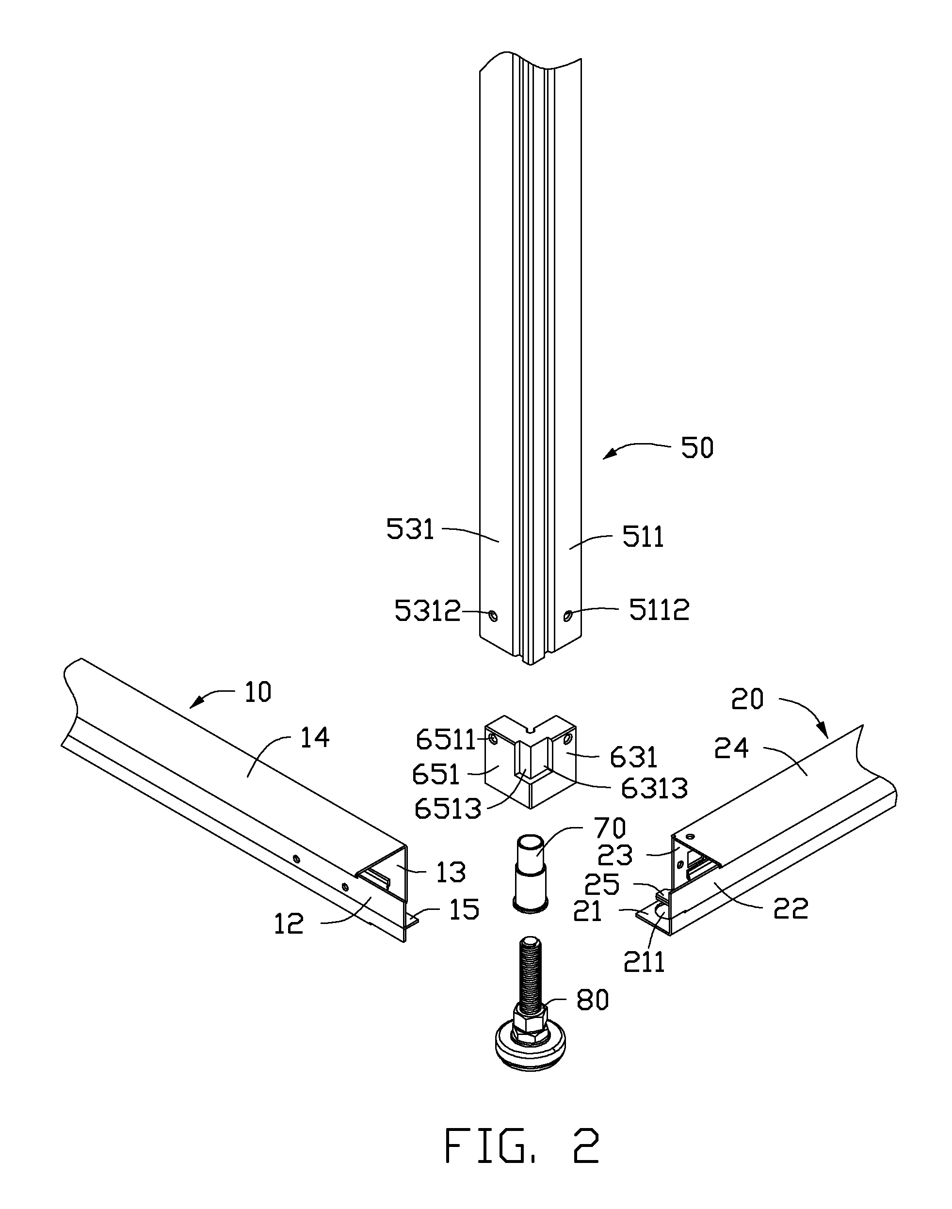
[0015]Referring to FIGS. 2-4, each first pole 10 includes a first base (not shown), a first side panel 12, and a second side panel 13 connected two op...


PUM


Abstract

A server rack assembly includes a frame, a support, and a securing component. The frame includes a first pole and a second pole. The support includes a first part and a second part. A first stopper portion is located on the first part, and a second stopper portion is located on the second part. The securing component includes a bottom portion mounted to the first and the second poles, a first securing portion and a second securing portion. A first positioning portion is disposed on the first securing portion, and a second positioning portion is disposed on the second securing portion. The first securing portion is attached to the first part, so the first positioning portion is engaged with the first stopper portion. The second securing portion is attached to the second part, so the second positioning portion is engaged with the second stopper portion.

Description

BACKGROUND[0001]1. Technical Field[0002]The present disclosure relates to electronic device enclosures, and more particularly to a server rack assembly.[0003]2. Description of Related Art[0004]Server system racks house electronic equipment such as network server systems, data storage devices, power supplies, and others. A server rack assembly generally includes two frames of the same configuration and four supports connected to the two frames. Each frame includes a first pole and a second pole. When the first pole is to be secured to the second pole and the support, a connecting component must synchronously connect to the first pole, the second pole and the support, an inconvenient requirement.BRIEF DESCRIPTION OF THE DRAWINGS[0005]Many aspects of the embodiments can be better understood with references to the following drawings. The components in the drawings are not necessarily drawn to scale, the emphasis instead being placed upon clearly illustrating the principles of the embodi...

Claims


Application Information

Patent Timeline
IPC IPC(8): A47B81/00A47B96/00
CPCH05K7/1488H02B1/014
Inventor FAN, CHEN-LU
Owner HON HAI PRECISION IND CO LTD
Why Eureka
Try Eureka