Control System in Vehicle

a control system and vehicle technology, applied in the direction of electric control, machines/engines, cycles, etc., can solve the problems of complex control, vehicle cannot start and accelerate smoothly, vehicle cannot start smoothly, etc., and achieve the effect of simplifying control

Active Publication Date: 2012-01-26
KAWASAKI MOTORS LTD
View PDF1 Cites 14 Cited by
  • Summary
  • Abstract
  • Description
  • Claims
  • Application Information

AI Technical Summary

Benefits of technology

[0011]The present invention addresses the above described condition, and an object of the present invention is to reflect a driver's operation of an accelerator or the like, on control of a driving power source to a great extent, while preventing the rotational speed of the driving power source from increasing in excess according to a driving state of a vehicle, and implementing smooth starting and acceleration, by using simplified control.
[0015]In brief, since the rotational speed limiting control is executed and terminated according to the driving state of the vehicle, it is possible to prevent the rotational speed of the driving power source from increasing in excess as necessary and implement smooth driving of the vehicle during starting, acceleration, or the like. In addition, the driver's operation of the accelerator or the like is reflected to a great extent on the control of the driving power source.
[0018]Preferably, the first state may further include a state where a second condition in which the driver has performed an operation for starting or accelerating the vehicle is met after the first condition is met. This allows the rotational speed limiting control to be performed more surely during starting or acceleration of the vehicle.
[0024]The rotational speed limiter reduces a torque of the driving power source according to a magnitude of a rotational speed deviation with respect to the upper limit value when the rotational speed of the driving power source exceeds the upper limit value. This makes it possible to decrease the engine speed to the upper limit value quickly.
[0025]The upper limit value of the rotational speed of the driving power source in the rotational speed limiting control may be set to increase according to a vehicle speed. This allows the engine speed to increase gradually as the vehicle speed increases gradually from zero during starting of the vehicle. This provides the driver a comfortable driving feeling.
[0026]The control system may further comprise a torque controller for controlling a torque of the driving power source according to at least one of a slip state of the drive wheel and a change state of the rotational speed of the driving power source, to execute general traction control, along with the rotational speed limiting control. This allows the drive wheel to be prevented from slipping to a great degree more surely.

Problems solved by technology

This may result in a situation where the vehicle cannot start smoothly.
Besides, due to such a rapid change in the driving power, the drive wheel slips for a moment and the resulting impact is transmitted to the driver as in the above case.
Under such a high engine speed condition, the vehicle cannot start and accelerate smoothly.
However, in the conventional traction control generally used, it is necessary to perform feed-back control of the output of the engine speed sensor, and such control is complex.
In addition, in the traction control, since the engine torque is reduced after the slip of the drive wheel has occurred, the impact cannot be mitigated sufficiently sometimes, which leaves room for improvement.
In the case where the engine speed is controlled irrespective of the driver's accelerator operation during starting, as disclosed in Japanese Laid-Open Patent Application Publication No. 2006-329118, the driver feels discomfort because the accelerator operation is not reflected well by the vehicle's behavior.
In the conventional example, since the engine speed is set considerably low to enable the vehicle to start smoothly even on the bad road surface or the like, the driver feels that the engine speed does not substantially increase regardless of the driver's operation of the accelerator or the like, and an engine stall could occur if the clutch is operated unskillfully by the driver.

Method used


Image

  • Control System in Vehicle
  • Control System in Vehicle
  • Control System in Vehicle

Examples


embodiment 1

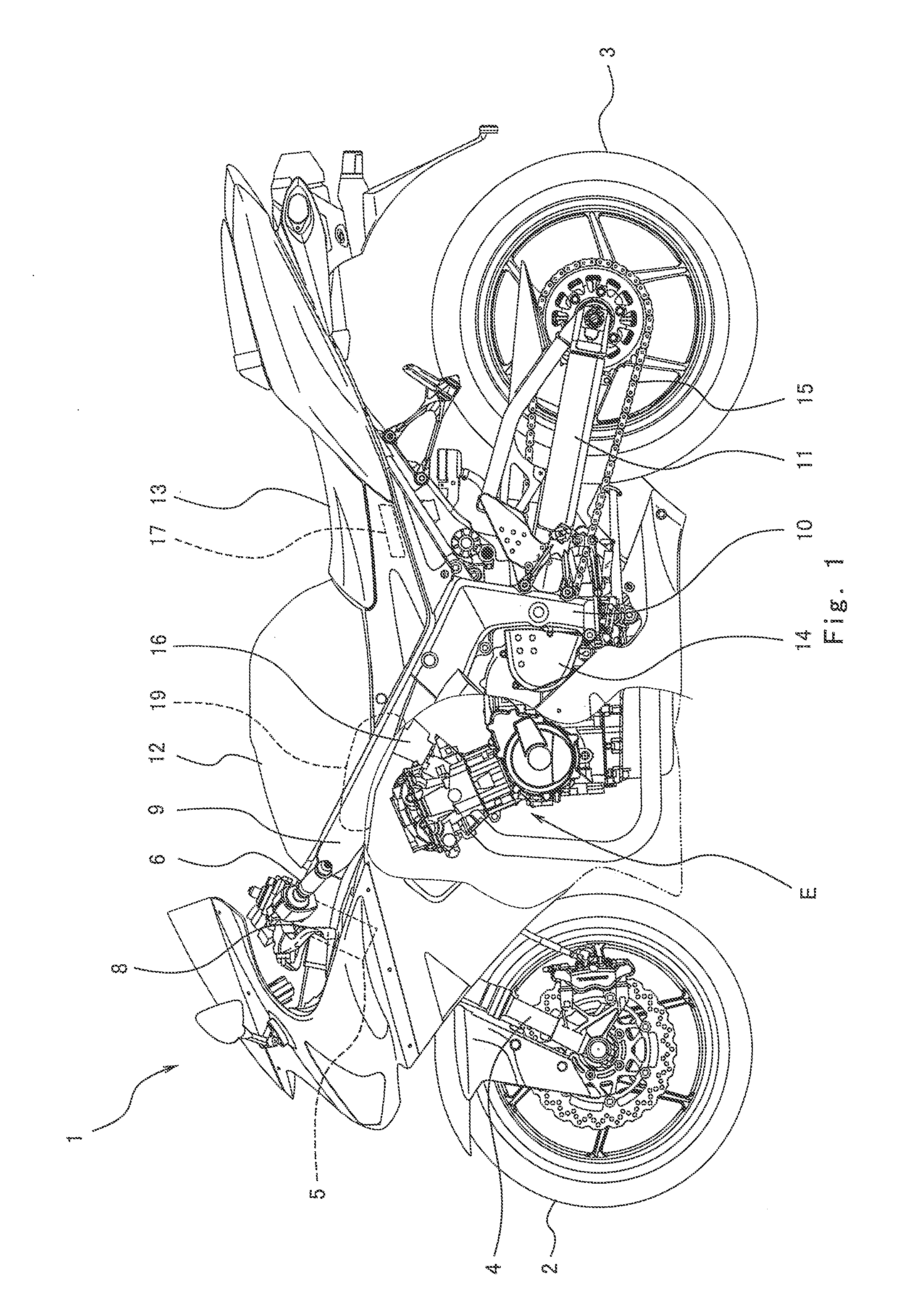
[0041]FIG. 1 is a left side view of a motorcycle 1 (vehicle) according to Embodiment 1 of the present invention. Referring now to FIG. 1, the motorcycle 1 includes a front wheel 2 which is a driven wheel and a rear wheel 3 which is a drive wheel. The front wheel 2 is rotatably mounted to the lower end portion of a front fork 4 extending substantially vertically. The front fork 4 is attached to a steering shaft (not shown) via brackets. The steering shaft is rotatably supported by a head pipe 5 provided at a vehicle body of the motorcycle 1.

[0042]A bar-type steering handle 6 extending in a rightward and leftward direction is attached to the brackets. The driver maneuvers the steering handle 6 to steer the front fork 4 and the front wheel 2. A throttle grip 7 (see FIG. 3) is provided at a right end portion of the steering handle 6 which is gripped by the driver's right hand. The throttle grip 7 is rotated by twisting the driver's wrist to operate a throttle device 16 as described late...


PUM


Abstract

A control system for controlling a driving power source in a vehicle, includes a driving state detector for detecting a driving state of the vehicle; a first determiner for determining whether or not the driving state detected by the driving state detector is a first state; a second determiner for determining whether or not the driving state detected by the driving state detector is a second state; a rotational speed limiter for executing rotational speed limiting control for limiting a driving power source rotational speed to a predetermined upper limit value or less when the first determiner determines that the driving state is the first state, during an operation of the driving power source; and a rotational speed limiting termination unit for terminating the rotational speed limiting control, when the second determiner determines that the driving state is the second state, during the operation of the driving power source.

Description

CROSS-REFERENCE TO RELATED APPLICATION[0001]The present application claims priority to and the benefit of Japanese Patent Application No. 2010-162867 filed on Jul. 20, 2010, which is hereby incorporated by reference in its entirety for all purposes.BACKGROUND ART[0002]1. Field of the Invention[0003]The present invention generally relates to control systems in vehicles such as motorcycles, ATVs (all terrain vehicles), or small trucks. More particularly, the present invention relates to control of driving power sources to improve drivers' feeling during, for example, starting of the vehicles.[0004]2. Description of the Related Art[0005]In general, a vehicle drives on a bad road surface or rough road surface of a gravel road, a muddy road, a sandy road, etc., as well as a good road surface of a dried pavement, etc. During driving on the bad road surface, a wheel's (or tire's) grip force on the road surface tends to be small. If an engine speed increases in excess during starting, the d...

Claims


Application Information

Patent Timeline
Patent Type & Authority Applications(United States)
IPC IPC(8): F02D9/02
CPCB60K28/16B60W2300/36F02B61/02F02D9/02F02D29/02F02D2200/702F02D41/022F02D41/10F02D2200/501F02D2200/602F02D41/0205
Inventor MATSUDA, YOSHIMOTO
Owner KAWASAKI MOTORS LTD
Why Eureka
Try Eureka