Apparatus and method for preventing an overshoot in the rotation speed of an internal-combustion engine

Active Publication Date: 2005-10-25
MITSUBISHI ELECTRIC CORP
View PDF4 Cites 2 Cited by
  • Summary
  • Abstract
  • Description
  • Claims
  • Application Information

AI Technical Summary

Benefits of technology

[0012]A second aspect of the invention provides an apparatus for preventing an overshoot in a rotation speed of an internal-combustion engine, includes a starter/battery charger and a controller. The starter/battery charger includes 3-phase armature coils, is connected to a crank shaft of the internal-combustion engine, operates as a starting motor for starting the internal-combustion engine, and also operates as a charging generator for charging a battery after the internal-combustion engine has been started. The controller performs a driving control for causing the starter/battery charger to generate positive torque and a braking control for causing the starter/battery charger to generate negative torque and thereby controlling the rotation speed of the internal-combustion engine. The controller causes the starter/battery charger to generate negative torque in the braking control by effecting short-circuiting between phases of the 3-phase armature coils of the starter/battery charger, to thereby prevent an overshoot in the rotation speed of the internal-combustion engine.
[0013]In this overshoot preventing apparatus, the controller causes the starter/battery charger to generate negative torque in the braking control by effecting short-circuiting between the phases of the 3-phase armature coils of the starter/battery charger. The short-circuiting between the phases of the 3-phase armature coils of the starter/battery charger allows, easily and effectively, the starter/battery charger to generate negative torque, and thereby makes it possible to prevent the overshoot in the rotation speed of the internal-combustion engine.
[0014]A third aspect of the invention provides a method for preventing an overshoot in a rotation speed of an internal-combustion engine, the method using a starter/battery charger and a controller. The starter/battery charger is coupled to a crank shaft of the internal-combustion engine, operates as a starter for starting the internal-combustion engine, and also operates as a battery charger for charging a battery after the internal-combustion engine has been started. The method includes the steps of carrying out a judgement that a self-ignition state has been established in the internal-combustion engine depends on one of the rotation speed of the internal-combustion engine and a variation rate of the rotation speed has exceeded a prescribed value during an engine starting operation; and switching a control on the starter/battery charger from a driving control to a braking control upon the judgement that the self-ignition state has been established in the internal-combustion engine, to thereby prevent the overshoot in the rotation speed of the internal-combu

Problems solved by technology

At an instant when self-ignition of the engine has just started, because of mechanical delays in the air system and the fuel system of the engine and delays in the control system that detects a rotation speed of the engine and issues instructions relating to an air supply rate, a fuel injection amount, and ignition timing in accordance with the detected rotation speed, torque is generated that is higher than necessitated to attain an idling rotation speed or a target rotation speed of an instruction from the controller of the engine, resulting in an overshoot in rotation speed.
Such an overshoot in the rotation speed of the engine causes a steep rise i

Method used


Image

  • Apparatus and method for preventing an overshoot in the rotation speed of an internal-combustion engine
  • Apparatus and method for preventing an overshoot in the rotation speed of an internal-combustion engine
  • Apparatus and method for preventing an overshoot in the rotation speed of an internal-combustion engine

Examples


Example

First Embodiment

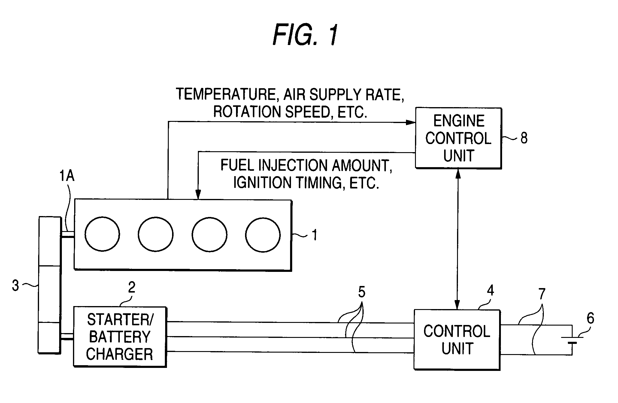
[0024]A first embodiment of the present invention will be described below with reference to FIG. 1. FIG. 1 is a schematic diagram showing a configuration and a method of the first embodiment. As shown in FIG. 1, a starter / battery charger 2 of an internal-combustion engine 1 is a 3-phase synchronous rotary machine, for example, which is coupled to a crank shaft 1A of the engine 1 via a belt 3. Alternatively, the starter / battery charger 2 may be coupled to the crank shaft 1A directly, that is, without intervention of the belt 3.

[0025]A control unit 4 for the starter / battery charger 2 is connected to the starter / battery charger 2 via 3-phase lines 5 that are connected to 3-phase armature coils, and controls the starter / battery charger 2 so that it can generate start drive torque (positive torque) or braking torque (negative torque).

[0026]A battery 6 that is connected to the control unit 4 via power lines 7 serves as a power source for the control unit 4. When the starte...

Example

Second Embodiment

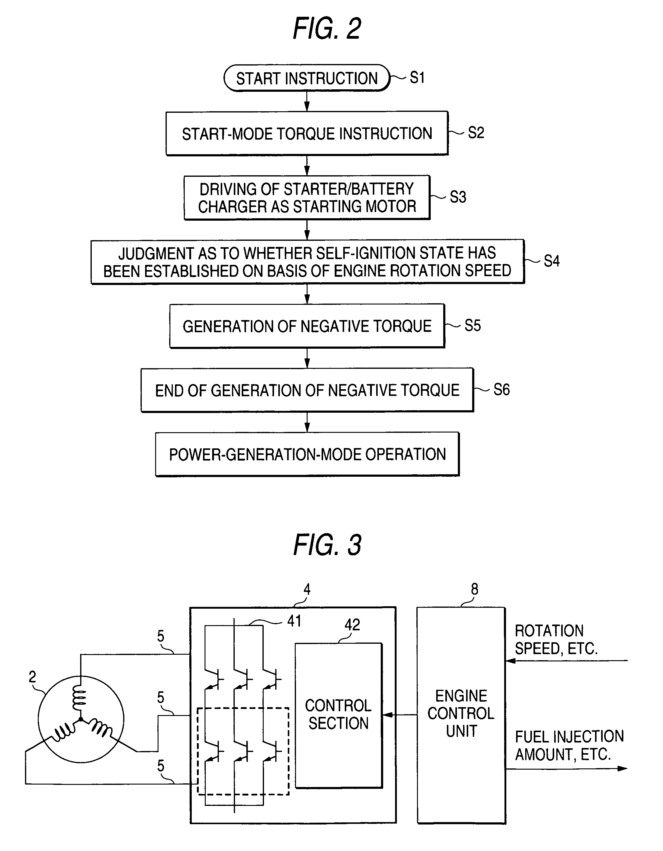
[0032]Next, a second embodiment of the invention will be described with reference to FIG. 3. FIG. 3 is a schematic diagram showing a starter / battery charger and its control unit according to the second embodiment. Components in FIG. 3 having the same or corresponding components in FIG. 1 are given the same reference numerals and will not be described.

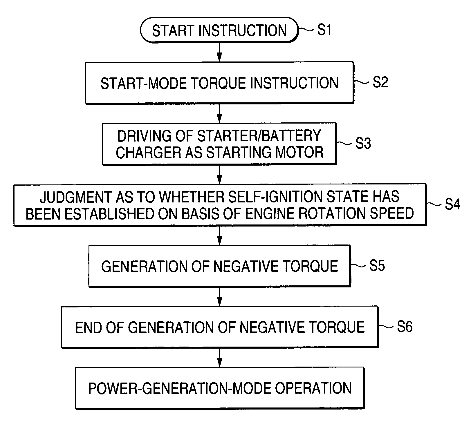
[0033]The control unit 4 for the starter / battery charger 2 includes an inverter section 41 consisting of arms of three respective phases in each of which a pair of switching elements are connected to each other in series. The control unit 4 also includes a control section 42 of the inverter section 41. The control unit 4 controls the supply of power to the starter / battery charger 2 on the basis of an instruction from the higher-rank control unit or the engine control unit 8. On the other hand, monitoring the rotation speed of the engine 1, the higher-rank control unit or the engine control unit 8 judges, in the above-de...

Example

Third Embodiment

[0035]Next, a third embodiment of the invention will be described with reference to FIG. 4. FIG. 4 is a schematic diagram showing a starter / battery charger and its control unit according to the third embodiment. Components in FIG. 4 having the same or corresponding components in FIG. 3 are given the same reference numerals and will not be described. This embodiment is different from the second embodiment of FIG. 3 in the following points. Switches 91 and 92 are provided between the armature 3-phase lines 5 for the 3-phase armature coils of the starter / battery charger 2. The switches 91 and 92 are closed in response to the engine self-ignition completion signal from the higher-rank control unit or the engine control unit 8 and a 3-phase short-circuited state is established for a prescribed time, during which the starter / battery charger 2 generates negative torque. This makes it possible to properly prevent the overshoot in the rotation speed of the engine 1.

[0036]In t...


PUM


Abstract

A starter/battery charger, which is coupled to an internal-combustion engine, operates as a starting motor for starting the engine and also operates as a charging generator for charging a battery after the engine has been started. Control unit controls the rotation speed of the engine by performing a driving control and a braking control on the starter/battery charger. The control unit carries out a judgement that a self-ignition state has been established in the engine depends on one of the rotation speed of the engine and a variation rate of the rotation speed has exceeded a prescribed value. The control unit switchs from the driving control to the braking control upon the judgement, thereby preventing the overshoot in the rotation speed of the engine.

Description

BACKGROUND OF THE INVENTION[0001]1. Field of the Invention[0002]The present invention relates to an apparatus and method for preventing an overshoot in the rotation speed of an internal-combustion engine.[0003]2. Description of the Related Art[0004]It is well known that an internal-combustion engine is started by rotating the crank shaft of the engine by means of a starter that is coupled to the engine. In general, the rotation speed of an internal-combustion engine is increased to 200 to 300 rpm at the time of a start and is thereafter increased further to a self-ignition rotation speed of the engine, that is, an idling rotation speed or a rotation speed of a control by a controller for the engine.[0005]In starting an internal-combustion engine, to improve the ignition performance in a range lower than an idling rotation speed, the controller for the engine performs a control of promoting a self-ignition-based operation by controlling the ignition timing and increasing a fuel suppl...

Claims


Application Information

Patent Timeline
IPC IPC(8): F02N11/08F02N11/04F02D41/06F02D29/06H02P3/22H02P9/04
CPCF02D41/062F02N11/04F02N11/0848H02P3/22F02D2200/1012F02N2200/022F02N2300/104F02D41/06
Inventor KURIBAYASHI, MASARUASAO, YOSHIHITO
Owner MITSUBISHI ELECTRIC CORP
Why Eureka
Try Eureka