Dispenser

Active Publication Date: 2012-02-16
CONOPCO INC D B A UNILEVER
View PDF2 Cites 1 Cited by
  • Summary
  • Abstract
  • Description
  • Claims
  • Application Information

AI Technical Summary

Benefits of technology

[0022]Such a platform combines a number of features that together enable ease of bottom filling into the barrel through the platform at the same time as enabling a reduced fraction of the stick material to be retained within the platform to still achieve at least a similar capability to retain the stick material during retraction as well as advancement. Beneficially, the invention design enables such improvement to be obtained without increasing the weight of material from which the platform is made.
[0063]Such an assembly process not only enables the spindle to be made separately from the rotor wheel, but also by virtue of the platform being pre-assembled with the spindle before assembly with the rotor wheel, the location of the platform at the bottom end of the spindle stabilises the spindle during insertion into the barrel and locates the spindle centrally so that the mounting operation can be carried out precisely.

Problems solved by technology

However, dispensers having a solid platform must be filled from the top, through the open end of the barrel, which runs the risk of spillage if the amount of material discharged into the barrel is not controlled very closely.
Moreover, the top surface of the stick material can present a rough appearance that does not appeal to consumers, so that a subsequent processing step is needed to create a smooth and acceptable appearance.
A number of problems have been identified in respect of stick dispensers in general and bottom fill stick dispensers in particular.
A tower, with or without flanges tends to dig into the skin to a much greater extent than does a flat or domed platform upper surface and is accordingly uncomfortable.
Accordingly, it is considered preferable to employ a skeletal platform, but that has the disadvantage of having to be deeper than a simple plate, so that the length of the barrel has to be increased to accommodate it.
However, the inventors have further realised that less platform material could equate to thinner elements in a skeletal platform, but thinness increases the risk of flexing, and flexing results in creating fault lines at the junction of stick material and platform element.
Thus, although the problem may be easy to state, the solution is not easy to obtain.
A further problem associated especially with bottom filling of stick dispensers, which commonly occurs under gravity or at a low pump pressure, is how to control the flow so as to ensure even filling, avoid air pockets and wasteful internal splashing and disruption to the flow as a result particularly of the material encountering the mounting for the spindle and / or particularly elements within the platform en route to the body of the barrel.
Such needs complicate any solution to maintaining stick adherence and / or reducing the use of resources.
Such drying out of the stick material often weakens the adherence of the material to the platform so that one or more seals are incorporated at the mounting of the wheel at the base of the barrel and of course the aperture in the wheel is normally plugged.
However, seals typically bridge parallel surfaces of the elements forming the mounting of wheel at the base, and this likewise introduces dead space in the barrel.
However, such a design requires an interior stop to be provided at the open end of the barrel.
It is possible to contemplate a design of the stop coupled with distortion of the barrel open end sufficient to permit insertion of the platform, but such a combination of stop design plus barrel distortion that permits insertion also runs a severe risk that the same extent of distortion would prevent the stop from functioning.
Not surprisingly, this design seems not to have been commercialised in the 15 years or so since it was devised.
Other and further problems associated with bottom fill stick dispensers relate to the dead space in between the base of the barrel and the platform.
Such space contributes to the weight of the package and in particular the weight of plastic needed to make the dispenser.

Method used


Image

  • Dispenser
  • Dispenser
  • Dispenser

Examples


Embodiment Construction

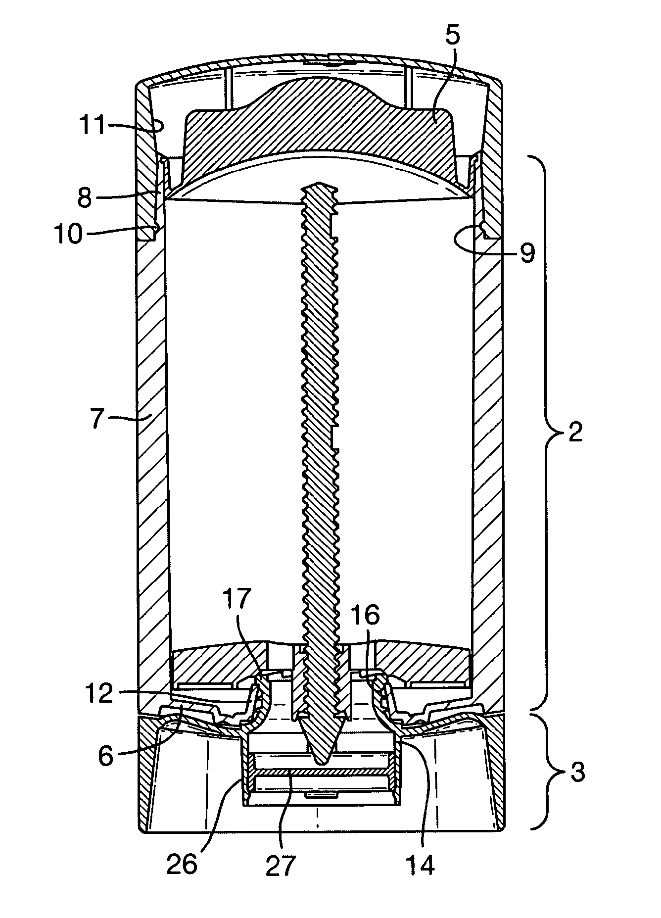
[0025]The present invention relates to a dispenser which comprises a skeletal platform and having a filling ring, fitting within a barrel and a rotor wheel mounted at the base of the barrel and having a boss extending within the base that is capable of abutting, edge to edge, the bottom of the intermediate ring.

[0026]In especially preferred embodiments, and in conjunction with the abutting ring and boss, the platform has a central threaded hub and disposed around the hub a multiplicity of walls, preferably concentric which in practice is at the centre of the hub or having a focal point for intermediate walls that is within the filling ring. The outermost wall or rim is oval. In this specification, oval indicates non-circular, having a major and minor axis, preferably symmetrical. Situate between the rim wall and the hub are at least two and preferably three elliptical walls. Herein elliptical can have a varied or constant radius, the latter being preferable and simply called circula...


PUM


Abstract

An oval dispenser for stick material suitable for being filled through its base comprises a skeletal platform having a threaded hub, a rim wall, a circular wall intermediate between the hub and the rim defining a filling zone and linked to the hub by at least two spokes and to the rim by at least two spokes, which latter spokes intersect at least one wall and preferably two walls spanning the rim and intermediate between the filling zone and the rim.

Description

[0001]The present invention relates to a dispenser for a cosmetic product, and in particular to a dispenser for a product in stick form.BACKGROUND AND PRIOR ART[0002]Cosmetic formulations (alternatively called compositions) or like materials can be topically applied to a surface, such as skin, in a variety of different physical forms, using a variety of different dispensers (applicators) of which one combination comprises a stick, made from firm, solid material, by which is meant a solid integral bar that retains its shape if removed from the dispenser. This is to be contrasted with soft solids that do not retain their shape if removed from the dispenser.[0003]A dispenser for sticks conventionally comprises a barrel that is open at one end within which a platform (sometimes alternatively called an elevator, godet or piston) can be advanced towards the open end. Such a dispenser often comprises a mechanism for advancing and commonly, though not always, also for retracting the platfor...

Claims


Application Information

Patent Timeline
IPC IPC(8): A45D40/04
CPCA45D40/04
InventorBAINES, ROGER ANTHONYBUNCE, MARTIN CHRISTOPHERMAWTUS, GEOFFREY STEPHENSZEKELY, ALEX SANDORULIK, JURAJ
OwnerCONOPCO INC D B A UNILEVER