Blood pump with separate mixed-flow and axial-flow impeller stages, components therefor and related methods

a blood pump and impeller technology, applied in the field of pumps, can solve the problems of retrograde leakage flow, strong disk friction loss, increased extent and rate of red blood cell damage, etc., and achieve the effects of low power consumption, high hydraulic efficiency, and uniform flow field

Active Publication Date: 2012-05-31
WORLD HEART
View PDF8 Cites 24 Cited by
  • Summary
  • Abstract
  • Description
  • Claims
  • Application Information

AI Technical Summary

Benefits of technology

[0017]In one embodiment, there be provided a rotordynamic blood pump and method comprising a flow path geometry characterized with high hydraulic efficiency, low power consumption, uniform flow fields, and low

Problems solved by technology

One adverse outcome of operating a rotor at high rotational speeds is a tendency for high turbulence flow characteristics within the blood (e.g., high shear stress) that increase the extent and rate of red blood cell damage.
Additionally, for centrifugal or mixed-flow blood pumps with shrouded impellers (i.e., a circumferentially revolved surface interconnecting the impeller blade tips), the fluid within the clearance space between a rotating front shroud and the stationary housing demonstrates a complex three-dimensional structure, leading to retrograde leakage flow and strong disk friction loss.
The combination of disk friction loss and the strong vortical flow not only lowers pump efficiency but also potentially induces hemolysis and thrombosis.
For centrifugal or mixed-flow blood pumps with unshrouded or semi-open impellers, the lack of a front shroud introduces a problem due to the blade tip leakage flow from pressure-side to suction-side of the blades which occurs through the clearance between the rotating blade tip and

Method used


Image

  • Blood pump with separate mixed-flow and axial-flow impeller stages, components therefor and related methods
  • Blood pump with separate mixed-flow and axial-flow impeller stages, components therefor and related methods
  • Blood pump with separate mixed-flow and axial-flow impeller stages, components therefor and related methods

Examples


Embodiment Construction

[0034]Embodiments are described more fully below in sufficient detail to enable those skilled in the art to practice the system and method. However, embodiments may be implemented in many different forms and the present invention should not be construed as being limited to the embodiments set forth herein. The following detailed description is, therefore, not to be taken to be limiting in any sense. For purpose of illustration, discussions of the technology will be made in reference to its utility as a cardiac assist blood pump. However, it is to be understood that the technology may have a variety of wide applications to many types of turbomachinery including, for example, commercial and industrial pumps, compressors, and turbines.

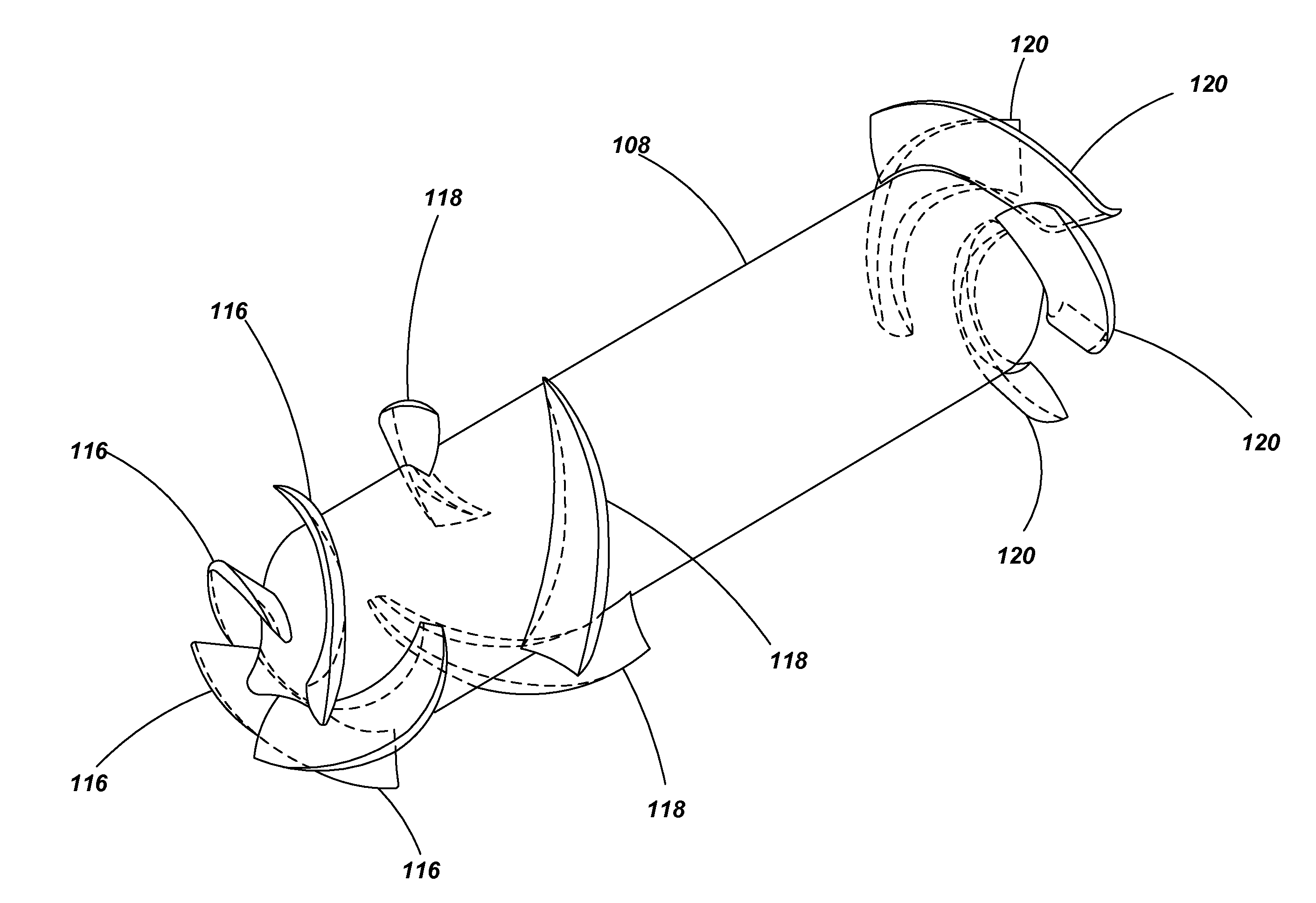
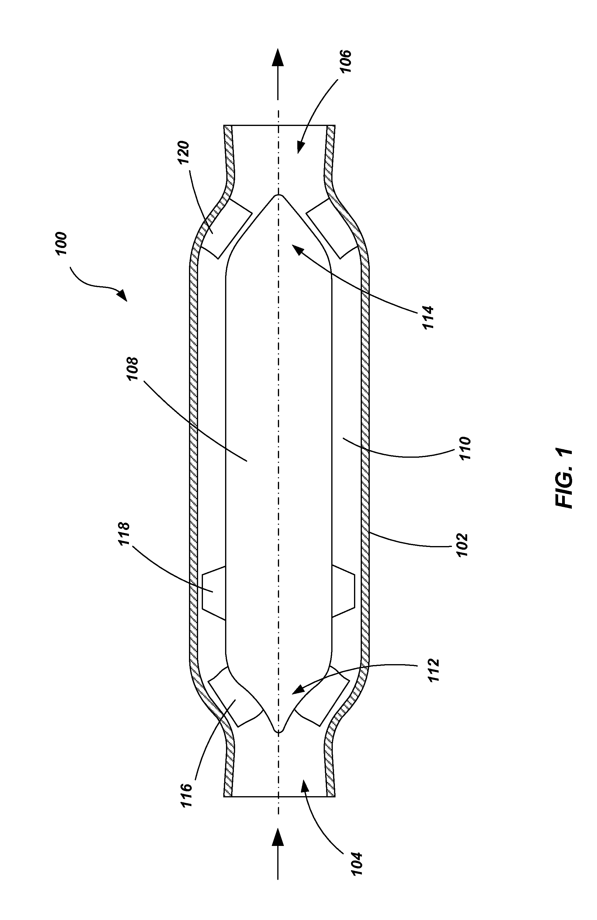
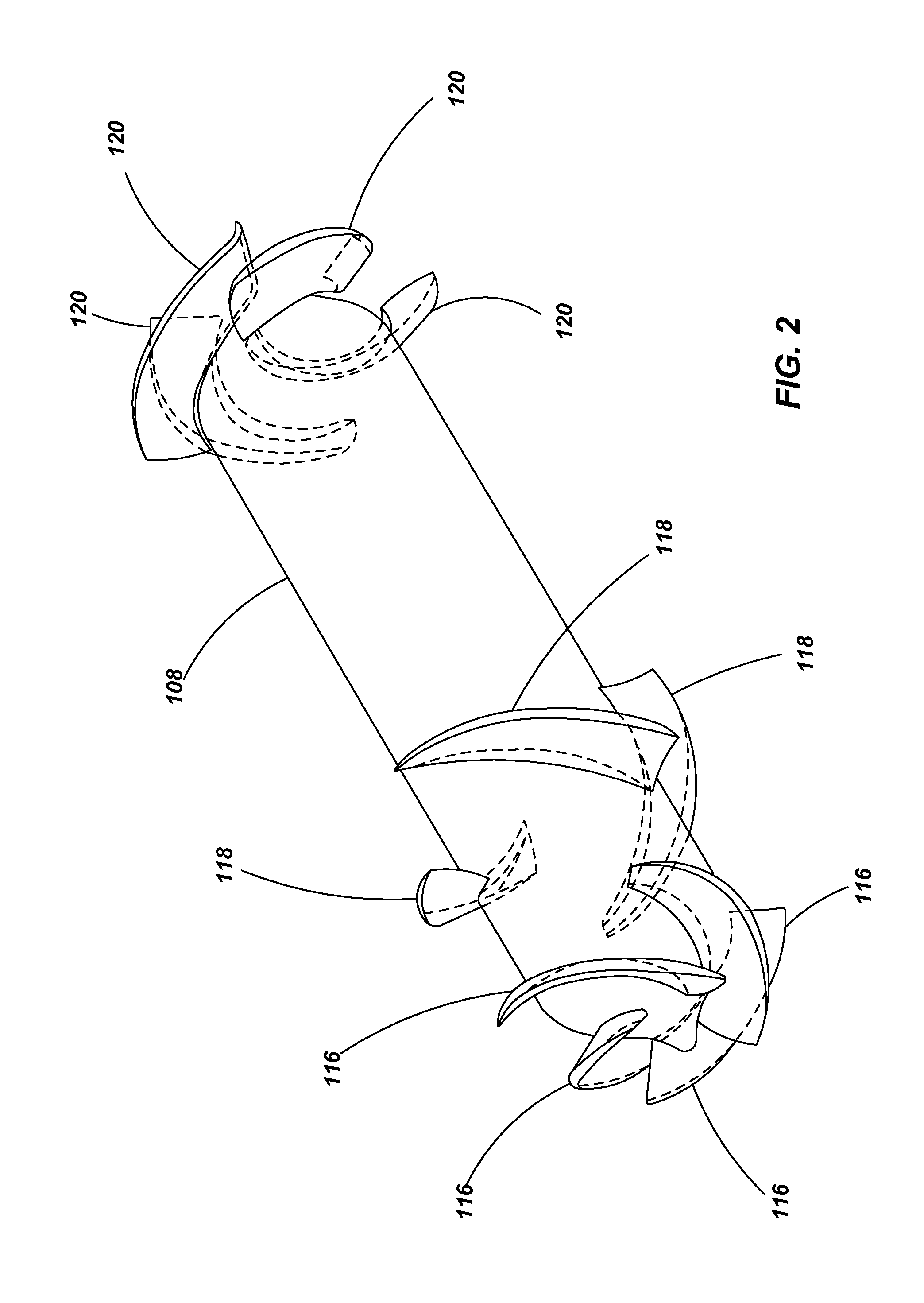
[0035]Referring to FIGS. 1 through 3, a rotordynamic blood pump 100 is shown in accordance with an embodiment of the present invention. FIG. 1 shows a meridional section of the pump 100. FIG. 2 shows a perspective view of various components of the pump, t...


PUM

PropertyMeasurementUnit
Lengthaaaaaaaaaa

Abstract

A rotordynamic pump for delivering continuous flow of fluids, such as blood, is provided. In one embodiment, the pump includes a stator housing having an inlet and an outlet. A rotor hub is disposed within the stator housing having a first, mixed-stage impeller and a second, axial-flow stage impellers. One or more stator vanes and extend radially inwardly from the stator housing. In one particular embodiment, the second stage impeller is disposed nearer to the outlet than to the inlet. The stator vanes may include a first set of stator vanes disposed between the first and second stage impellers, and a second set of stator vanes positioned between the second stage impellers and the outlet.

Description

CROSS-REFERENCE TO RELATED APPLICATIONS[0001]This application claims priority to U.S. Provisional Patent Application No. 61 / 394,213 filed Oct. 18, 2010, entitled BLOOD PUMP WITH SEPARATE MIXED-FLOW AND AXIAL FLOW IMPELLER STAGES. This application also claims priority to U.S. Provisional Patent Application No. 61 / 394,220, filed Oct. 18, 2010, entitled BLOOD PUMP WITH SPLITTER IMPELLER BLADES AND SPLITTER STATOR BLADES. The disclosures of the above-referenced priority applications are incorporated by reference herein in their entireties.TECHNICAL FIELD[0002]This invention relates generally to pumps. More specifically, this invention relates to blood pumps, such as cardiac assist pumps that may be implanted in a patient.BACKGROUND OF THE INVENTION[0003]Rotordynamic pumps, such as centrifugal, mixed-flow, and axial-flow pumps with mechanical bearings or magnetically suspended systems, have been widely used as a ventricular assist devices to support patients with heart diseases. In magne...

Claims


Application Information

Patent Timeline
IPC IPC(8): F04D7/00B23P11/00B23P15/02F04D3/00A61M60/178A61M60/221A61M60/237A61M60/806
CPCA61M1/101Y10T29/49245F04D3/00A61M1/125A61M60/148A61M60/237A61M60/178A61M60/806A61M60/221
Inventor WU, JINGCHUNVERKAIK, JOSIAH
Owner WORLD HEART
Why Eureka
Try Eureka