Measuring apparatus

a technology of measuring apparatus and probe, which is applied in the field of measuring apparatus, can solve the problems of difficult to bring the reception surface of the probe into complete contact with the subject's surface, and achieve the effect of reducing resolution

Inactive Publication Date: 2012-07-26
CANON KK
View PDF6 Cites 17 Cited by
  • Summary
  • Abstract
  • Description
  • Claims
  • Application Information

AI Technical Summary

Benefits of technology

[0009]Thus, image data in which reduction in resolution due to refraction of the acoustic wave is small

Problems solved by technology

However, in the case where the subject has a complex external shape, for example, in the case where the subject is a small animal

Method used


Image

  • Measuring apparatus
  • Measuring apparatus
  • Measuring apparatus

Examples


first embodiment

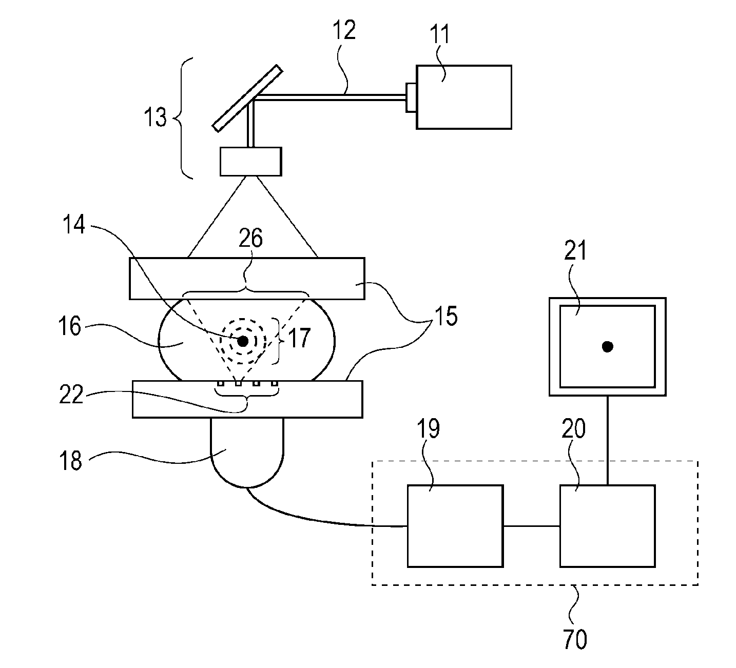
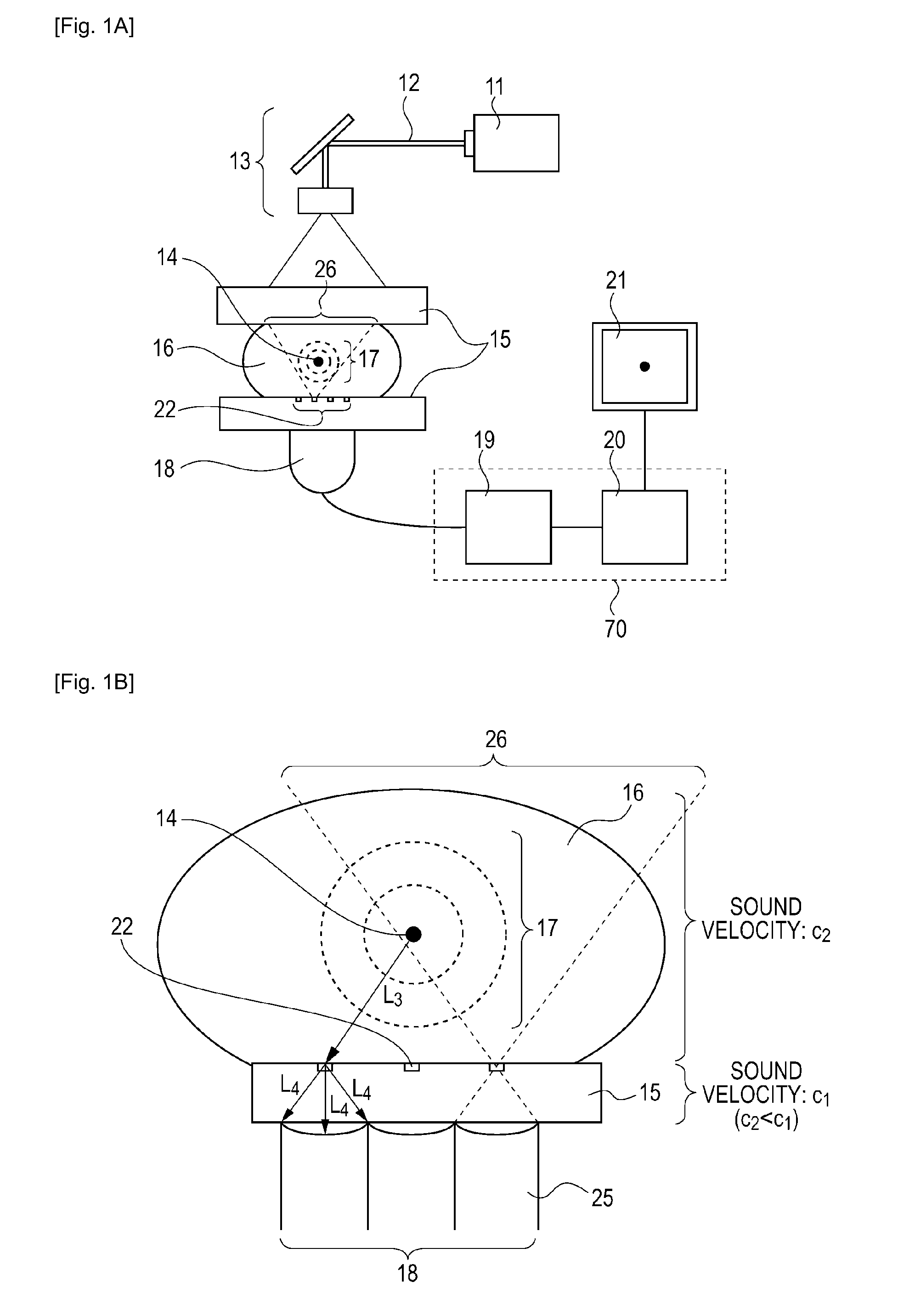
[0026]A first embodiment of the present invention will be described with reference to FIGS. 1A and 1B. FIG. 1A is a schematic diagram illustrating an example of a measuring apparatus to which the present invention can be applied. FIG. 1B is an enlarged schematic diagram illustrating the structure of a probe and a shape maintaining member for explaining a virtual detection region. In the present embodiment, a PAT apparatus that uses photoacoustic tomography is described as an example. The PAT apparatus generates image data by receiving an acoustic wave generated in a subject when the subject is irradiated with a light pulse.

[0027]The PAT apparatus according to the present embodiment includes a light source 11, an optical component 13, a pressing plate 15 that serves as a shape maintaining member, a probe 18, and a processing unit 70. Image data is generated by the processing unit 70, and is displayed by a display device 21. The processing unit 70 includes a signal processor 19 and an...

second embodiment

[0049]In a second embodiment, as illustrated in FIG. 4, a filter 47 having an opening 51 is provided on a shape maintaining member 48. The second embodiment differs from the first embodiment in that the opening 51 defines a virtual detection region 46 and an element is divided into a plurality of reception surfaces.

[0050]As illustrated in FIG. 4, the filter 47 having the physical opening 51 and made of a material that reflects or absorbs ultrasonic reflective waves is provided on the shape maintaining member 48. An acoustic wave that passes through the opening 51 is received by an element 52. The element 52 is divided into a plurality of reception surfaces 49. The acoustic wave is received by the reception surfaces and is converted into a plurality of electric signals (detected signals) 50. Then, a processing unit performs a delay process on the basis of distances a1 to a5 from the opening to the reception surfaces and adds the detected signals 50. The delay process is performed to ...

third embodiment

[0054]In the first and second embodiments, the PAT apparatus using photoacoustic tomography that receives an acoustic wave generated in a subject in response to irradiation of the subject with light is described in detail. However, the same principle can also be applied to a measuring apparatus (ultrasonic apparatus) which generates image data by transmitting an acoustic wave (typically an ultrasonic wave) from a probe and receiving an acoustic wave that has been reflected in the subject. In this case, similar to the first and second embodiments, the virtual detection region can be used in a receiving process. In addition, also in a process of transmitting the acoustic wave, the virtual detection region can be used as an virtual transmission region. The above-described virtual detection region directly serves as the virtual transmission region, and the ultrasonic wave can be transmitted as if it is transmitted from the virtual transmission region (virtual detection region). As a res...


PUM


Abstract

A measuring apparatus includes a shape maintaining member that maintains a shape of at least a part of a subject, an element that receives an acoustic wave through the shape maintaining member and converts the acoustic wave into a first electric signal, the acoustic wave being generated in the subject when the subject is irradiated with light, and a processing unit that generates image data using the first electric signal. The processing unit determines, on the basis of the first electric signal, a first time from when the acoustic wave is generated in the subject to when the acoustic wave reaches a reception surface of the element. The processing unit converts the first electric signal into a second electric signal using a difference between the first time and a second time in which the acoustic wave travels from a virtual detection region set near a subject-side surface of the shape maintaining member to the reception surface of the element, the second electric signal being assumed to have been obtained by receiving the acoustic wave at the virtual detection region.

Description

TECHNICAL FIELD[0001]The present invention relates to measuring apparatuses. More particularly, the present invention relates to a measuring apparatus that receives an acoustic wave that has been propagated through a subject and generates image data.BACKGROUND ART[0002]In the medical field, researches on measuring apparatuses that generate image data on the basis of information about the inside of a subject, such as a living body, using light emitted from a light source, such as laser, to irradiate the subject have been actively conducted. A photoacoustic tomography (PAT) apparatus is an example of such a measuring apparatus. In photoacoustic tomography, a subject is irradiated with light emitted from a light source, so that the light is propagated and diffused in the subject. A biological tissue in the subject absorbs energy of the light and generates an acoustic wave (typically an ultrasonic wave). The acoustic wave is received by a probe, so that an electric signal is obtained. T...

Claims


Application Information

Patent Timeline
IPC IPC(8): A61B6/00
CPCA61B5/0091A61B5/0095G01S7/52049A61B8/0825G01N21/1702A61B5/4312
Inventor FUKUTANI, KAZUHIKOKOBAYASHI, SHUICHI
Owner CANON KK
Why Eureka
Try Eureka