

Method and Apparatus for Application of Mortar
- Summary
- Abstract
- Description
- Claims
- Application Information
AI Technical Summary
Benefits of technology
Problems solved by technology
Method used
Image

Examples
Embodiment Construction
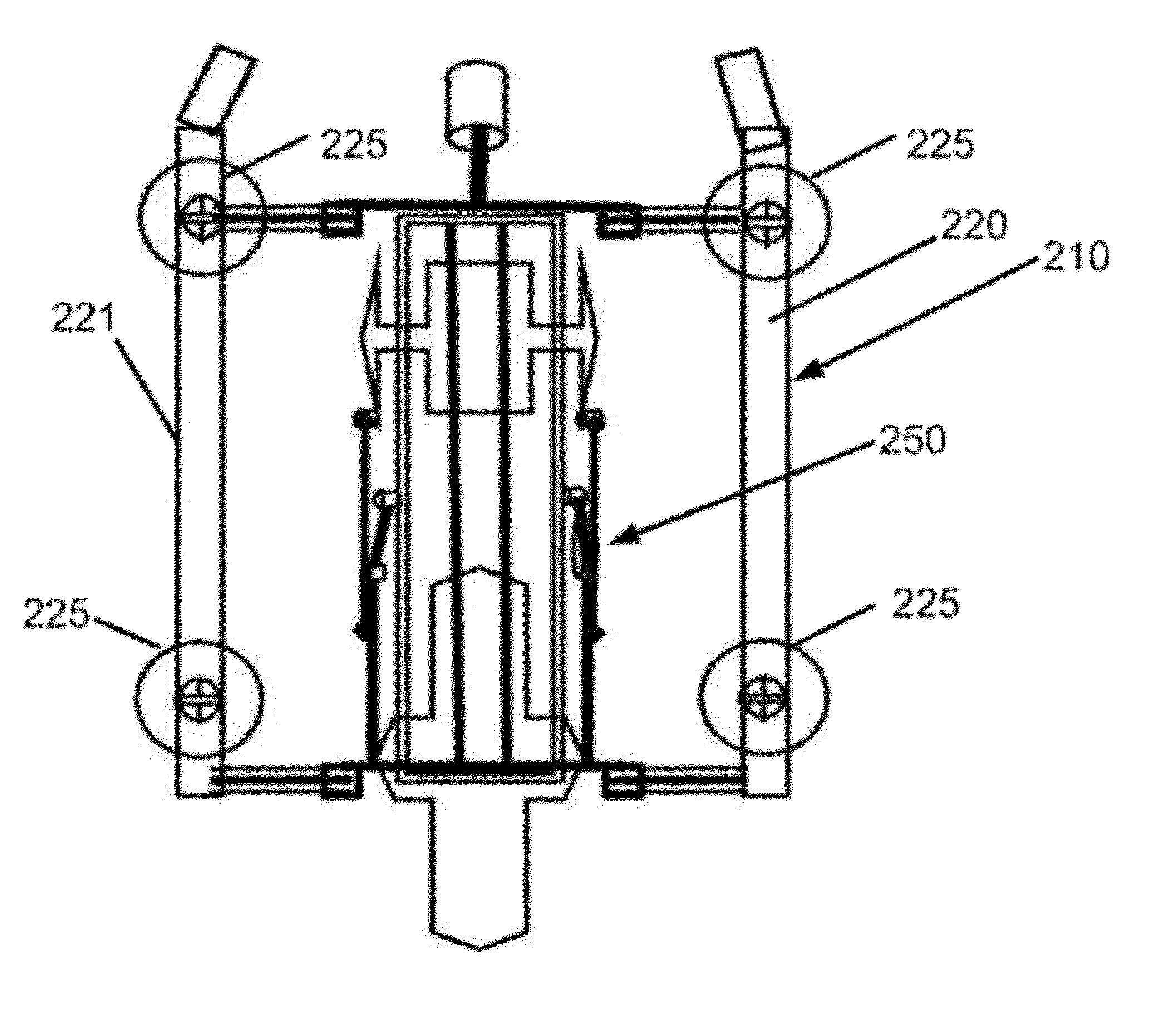
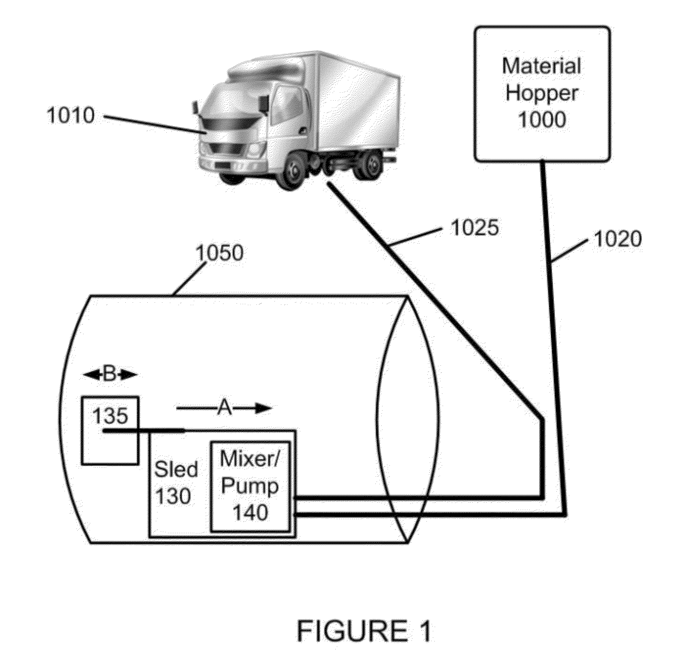
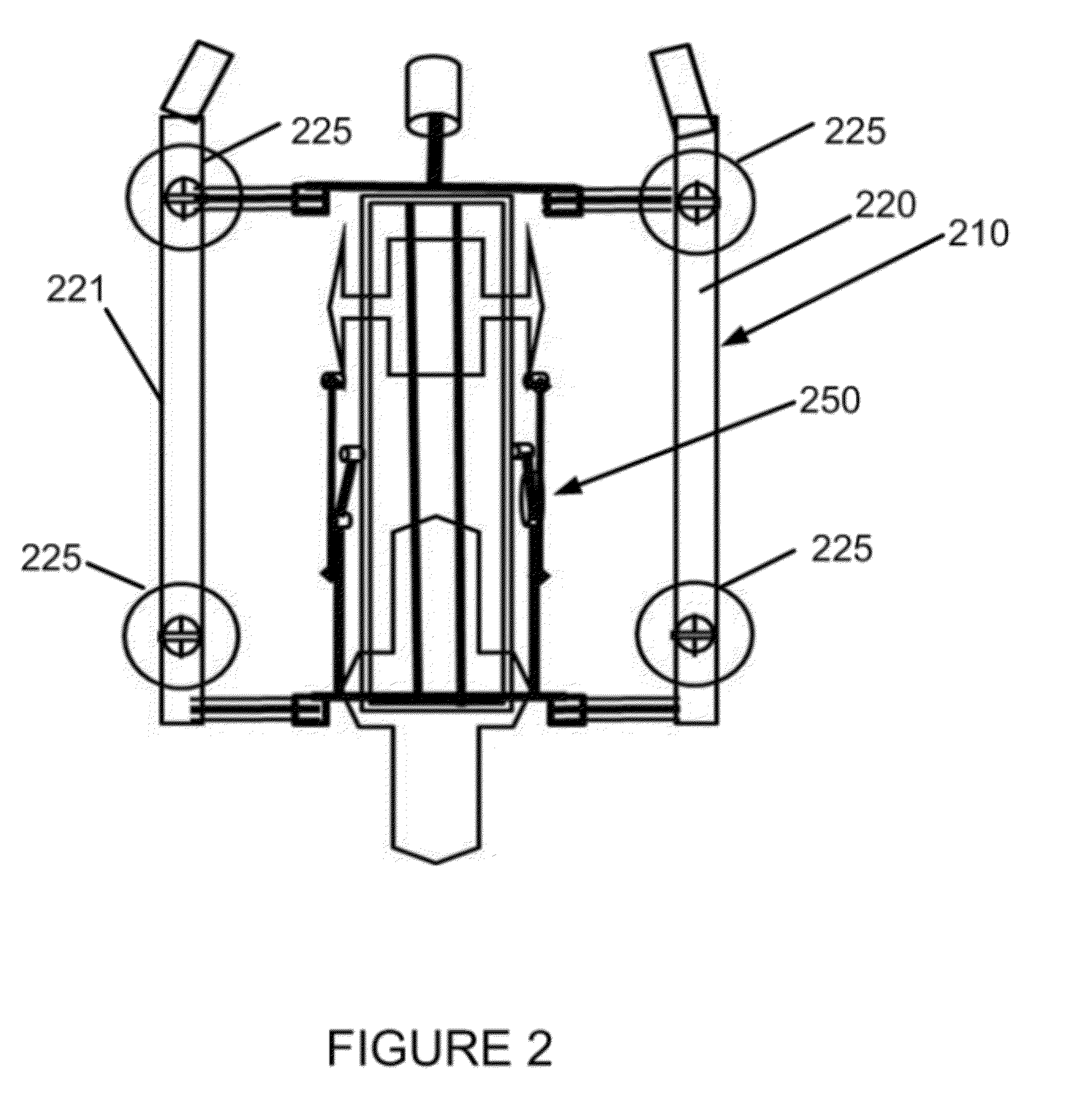
[0030]The invention will now be described making reference to the following drawings in which like reference numbers denote like structure or steps. In accordance with various embodiments of the invention, an inventive mortar may be applied in accordance with an inventive application method, employing an inventive application apparatus in order to address failures in pipes or other substances where access may be limited. Such inventive methods and systems may employ mixing of mortar material outside of a remediation area, delivery of one or more components thereof to be mixed in the vicinity of the remediation area, and preferred final placement of mortar material to an area in which there is limited or confined space access. The thoroughly mixed material may then preferably be applied through a high speed centrifugal sprayer or nozzle apparatus in a manner that produces a thick to thin overlaying fully compacted, consolidated composite.
[0031]The inventors of the present invention h...
PUM
 Abstract
Description
Claims
Application Information