Sealant mold fixture for a domed cap

a mold fixture and domed cap technology, applied in the field of sealing molds, can solve the problems of unremovable mold devices, unfavorable aircraft use of sealing attachment interfaces, and undesirable weight addition to aircraft, and achieve the effect of reducing the number of molds

Active Publication Date: 2012-08-30
PHYSICAL SYST
View PDF9 Cites 45 Cited by
  • Summary
  • Abstract
  • Description
  • Claims
  • Application Information

AI Technical Summary

Benefits of technology

[0006]In accordance with the invention, a sealant mold is provided for sealing a domed nutplate unit or the like particularly at a lower region thereof about an interface between the nutplate unit and a substrate such as a wall of an aircraft fuel tank or the like. The sealant mold is formed from a lightweight plastic material, and includes an inner cap in combination with an outer skirt to define a gap or trough for receiving and supporting a metered quantity of a curable sealant material. The mold is fitted onto a protective dome of the nutplate unit or the like with an inboard edge of the inner cap landed onto a dome shoulder. The outer skirt is then displaced downwardly about the landed inner cap in a direction toward the substrate to extrude the sealant material about the lower region of the nutplate unit particularly such as the attachment interface thereof with the substrate. The sealant material is allowed to cure, after which the sealant mold including the inner cap and the outer skirt can be stripped quickly and easily from the cured sealant material.

Problems solved by technology

However, in a modern aircraft environment, it is also important to note that additional weight added to the aircraft for use in sealing the attachment interface can be undesirable for its negative impact on overall fuel efficiency.
However, the existing mold devices generally apply an excess amount of sealant material to cover substantially the entire nutplate unit within the fuel tank, and these mold devices are not adapted for convenient removal following curing of the sealant material.
Accordingly, the excess amount of sealant material in combination with the non-removable mold devices contributes to undesired weight addition to the aircraft.

Method used


Image

  • Sealant mold fixture for a domed cap
  • Sealant mold fixture for a domed cap
  • Sealant mold fixture for a domed cap

Examples


Embodiment Construction

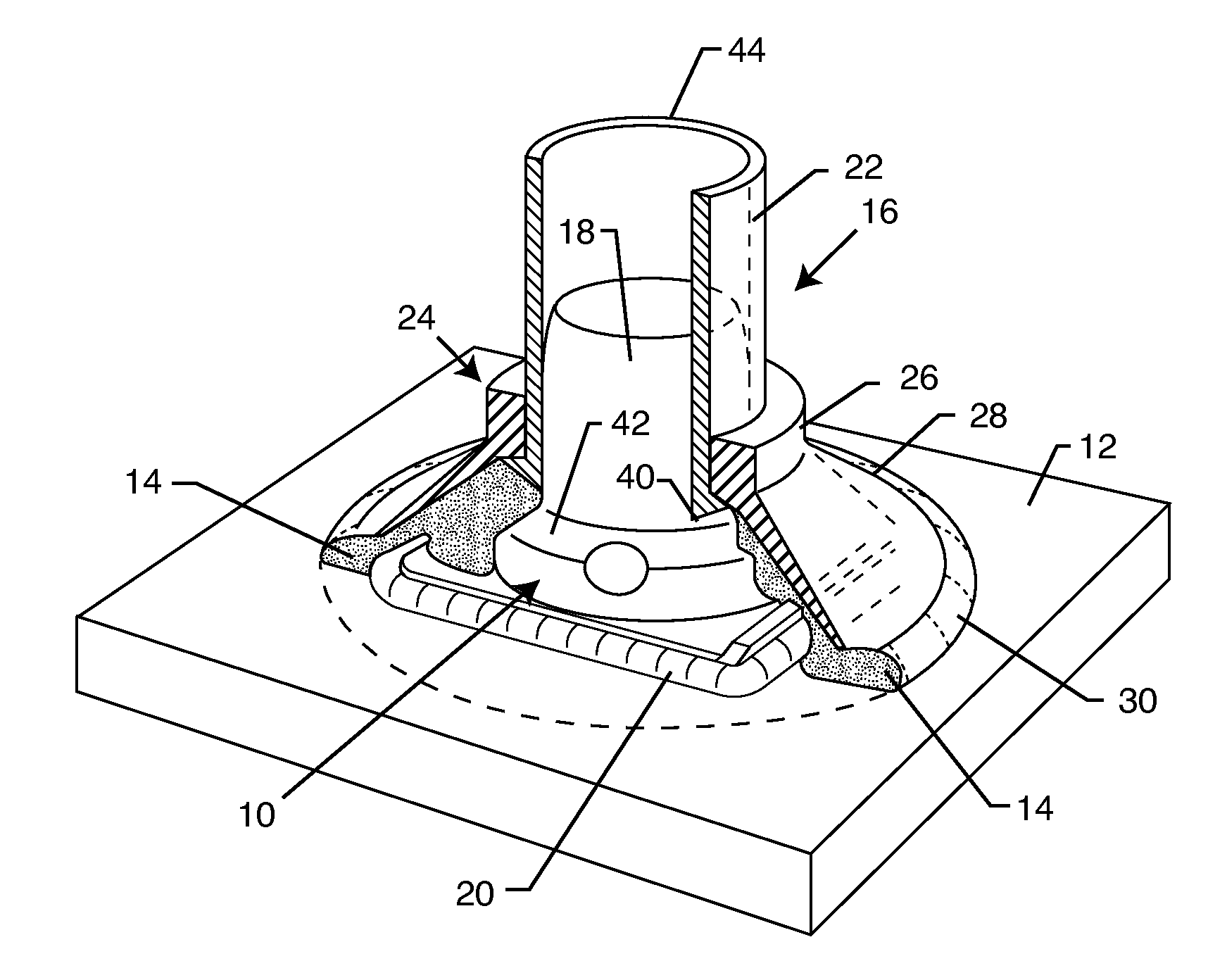
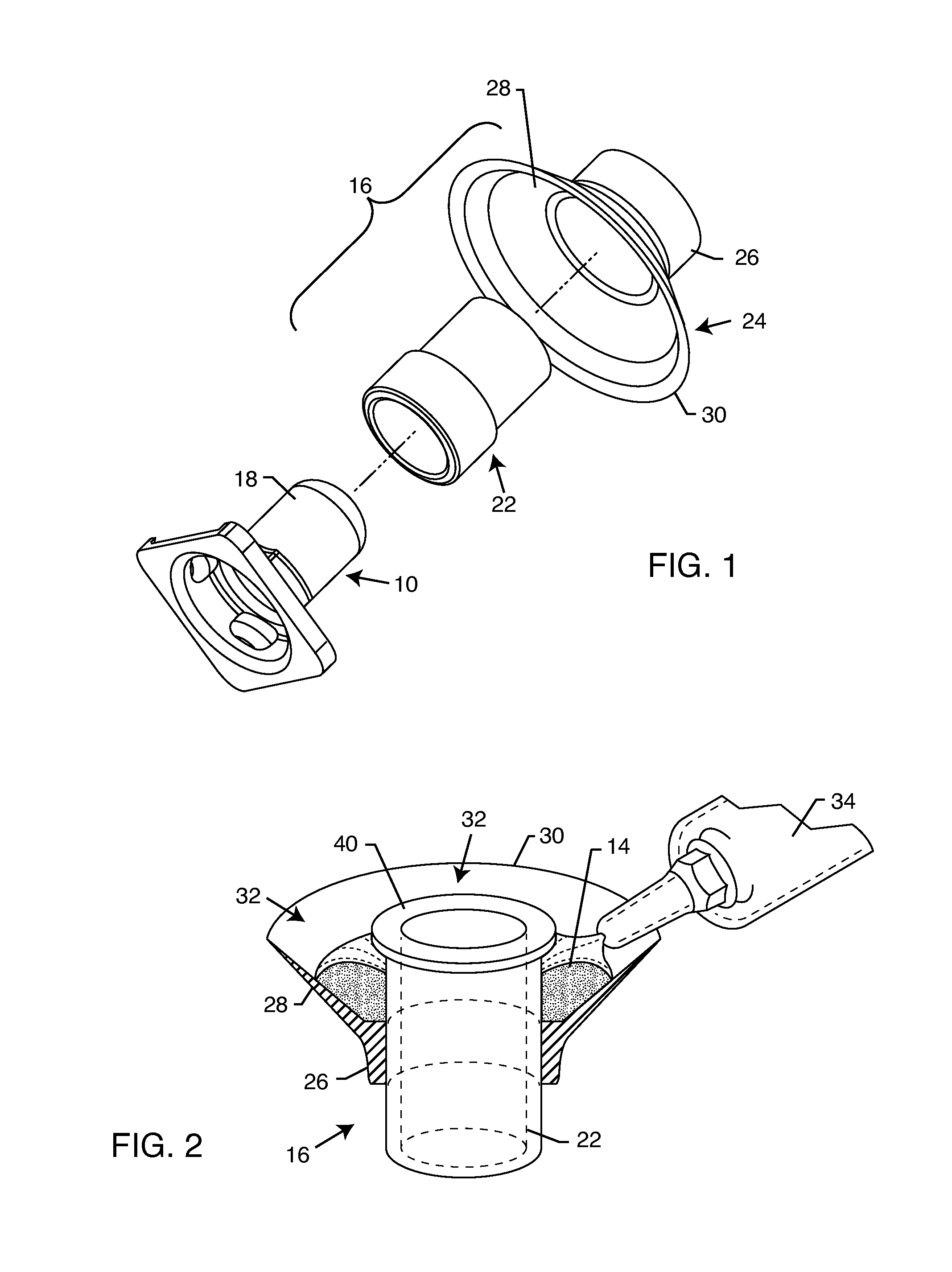
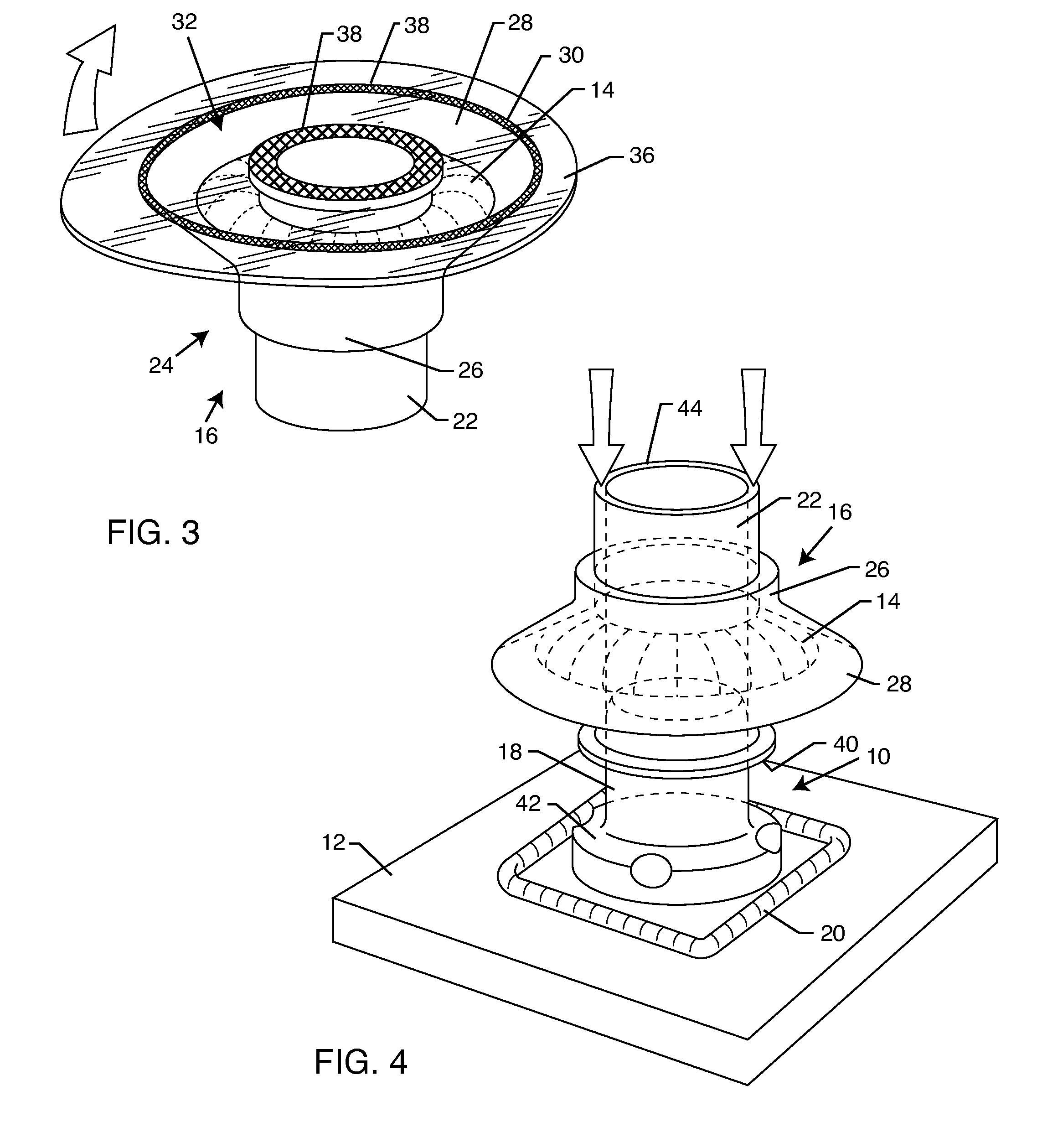
[0027]As shown in the exemplary drawings, a domed nutplate unit 10 or the like (FIGS. 1, 4 and 6-7) mounted onto a selected substrate 12 (FIGS. 4-7) is effectively and relatively quickly sealed by means of a curable sealant material 14 (FIGS. 2-7) applied by a sealant mold 16 (FIGS. 1-7) of the present invention. The sealant material 14, when cured, is applied in a limited amount and a controlled but substantially minimum and uniform thickness layer for securely coating and covering an attachment interface between the domed nutplate unit 10 or the like and the substrate 12. That is, the cured sealant material effectively seals between the substrate 12 and a dome 18 (FIGS. 4, 6 and 7) of the nutplate unit 10 or the like to safeguard the sealed attachment interface against degradation or fluid leakage. After the sealant material is substantially completely cured, the sealant mold 16 of the present invention is stripped quickly and easily from the cured sealant material 14 (FIG. 7), wh...


PUM

PropertyMeasurementUnit
sizeaaaaaaaaaa
weightaaaaaaaaaa
thicknessaaaaaaaaaa

Abstract

A sealant mold for sealing a domed nutplate unit particularly at a lower region about an adhesively attached interface with a substrate such as an aircraft fuel tank wall. The sealant mold is formed from a lightweight plastic material, and includes an inner cap in combination with an outer skirt to define a gap or trough for receiving and supporting a metered quantity of a curable sealant material. The mold is fitted onto a dome of the nutplate unit with an inner cap inboard edge landed onto a dome shoulder. The outer skirt is then displaced downwardly about the landed inner cap to extrude the sealant material about the lower region of the nutplate unit particularly such as the adhesively attached interface with the substrate. The sealant material is allowed to cure, after which the sealant mold can be stripped quickly and easily from the cured sealant material.

Description

BACKGROUND OF THE INVENTION[0001]This invention relates generally to a sealant mold for use with a domed nutplate unit or the like for sealing a lower portion of the nutplate unit particularly such as an adhesively mounted interface with a substrate against exposure to undesirable fluids and the like. More particularly, this invention relates to an improved sealant mold and related method of use wherein the lower portion of a domed nutplate unit or the like is effectively sealed with a minimum weight addition.[0002]Domed nutplate units and the like are generally known in the art, wherein a nutplate or other selected fastener device is encased within a dome or dome element to prevent contact with fluids present on one side of the dome. The fastener device is typically mounted onto a selected substrate, such as the wall of an aircraft fuel tank or the like, wherein the dome further is intended to prevent leakage of fluid such as aircraft fuel through a substrate bolt hole or the like ...

Claims


Application Information

Patent Timeline
Patent Type & Authority Applications(United States)
IPC IPC(8): B29C33/40
CPCB29L2031/773B29C33/40B29D99/0085Y10T156/1798B29C39/10B29C39/26B29L2031/26B29C33/00B29C39/028
Inventor HUTTER, III, CHARLES G.
Owner PHYSICAL SYST
Why Eureka
Try Eureka