Heat-dissipating module and lamp having the same

Inactive Publication Date: 2012-10-11
CHICONY POWER TECH CO LTD
View PDF1 Cites 12 Cited by
  • Summary
  • Abstract
  • Description
  • Claims
  • Application Information

AI Technical Summary

Benefits of technology

[0019]The base plate of the heat-dissipating module is made of sheet metal, for example, by stamping or pressing rather than by aluminum extrusion, so that the base plate made of a flat sheet metal can be easily pressed and bent to form the fins, thereby producing a three-dimensional heat-dissipating module with a reduced working hours and cost.
[0020]Since the heat-dissipating module of the present invention is made of sheet metal, the heat-dissipating module has a small thickness and light weight. Further, the base plate is formed by pressing sheet metal, which can increase the flatness of the base plate greatly. Thus, the base plate can be brought into flat contact with a heat source without using heat-conducting paste.
[0021]In the heat-dissipating module of the present invention, since the region among the bending sections and the base plate is hollowed to form a plurality of airflow channels, the airf

Problems solved by technology

However, each LED generates heat when emitting light.
As a result, electronic components in the LED will suffer damage or even burn down.
However, such a conventional heat-dissipating module has the following problems.
First, since the conventional heat-dissipating module is made by aluminum extrusion, a greater amount of aluminum material has to be used, which increases the weight of the heat-dissipating module.
Second, during the manufacturing process, the traditional aluminum-extruded heat-dissipating module is subjected to an extending step and a

Method used


Image

  • Heat-dissipating module and lamp having the same
  • Heat-dissipating module and lamp having the same
  • Heat-dissipating module and lamp having the same

Examples


Embodiment Construction

[0031]The detailed description and technical contents of the present invention will become apparent with the following detailed description accompanied with related drawings. It is noteworthy to point out that the drawings is provided for the illustration purpose only, but not intended for limiting the scope of the present invention.

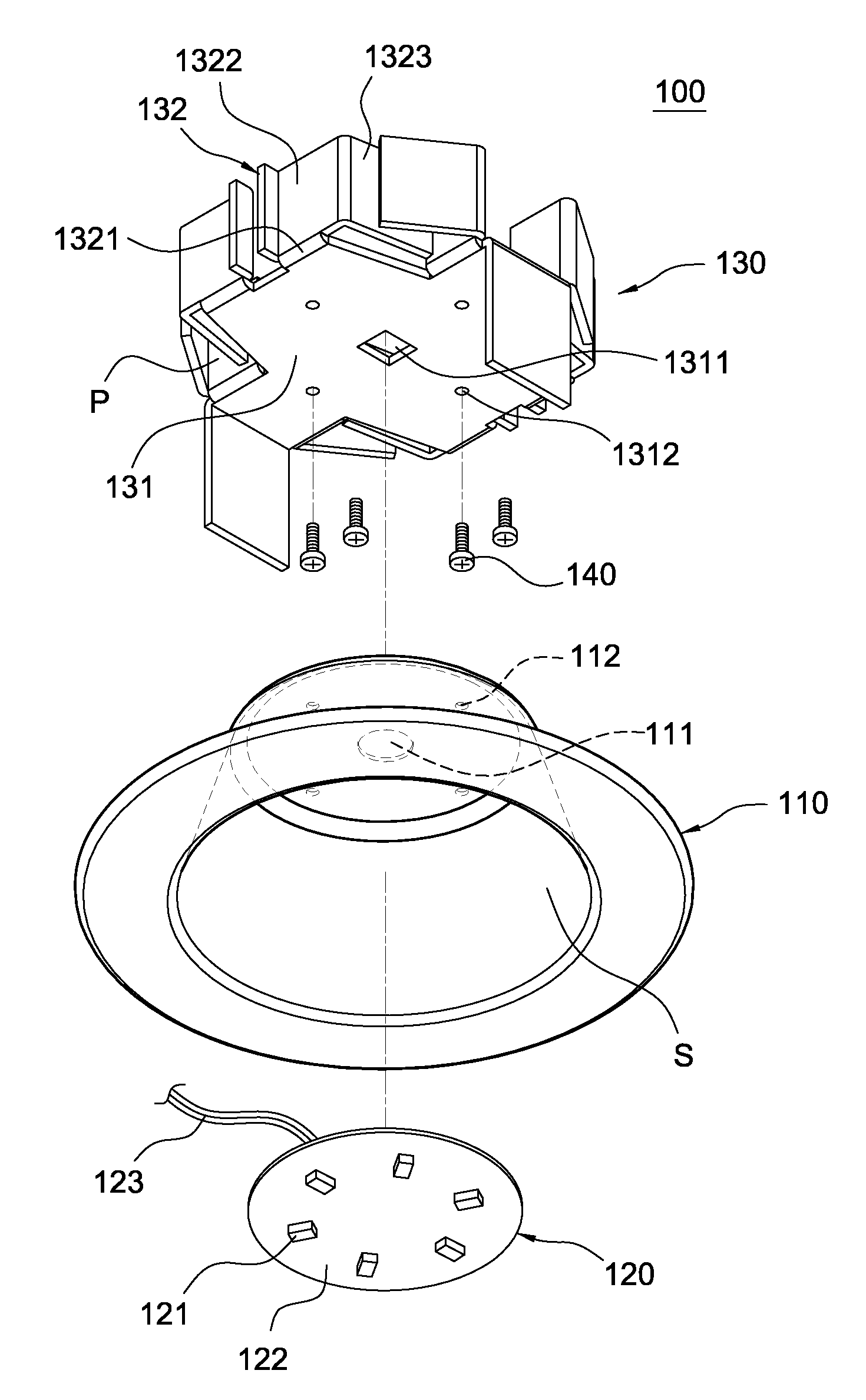
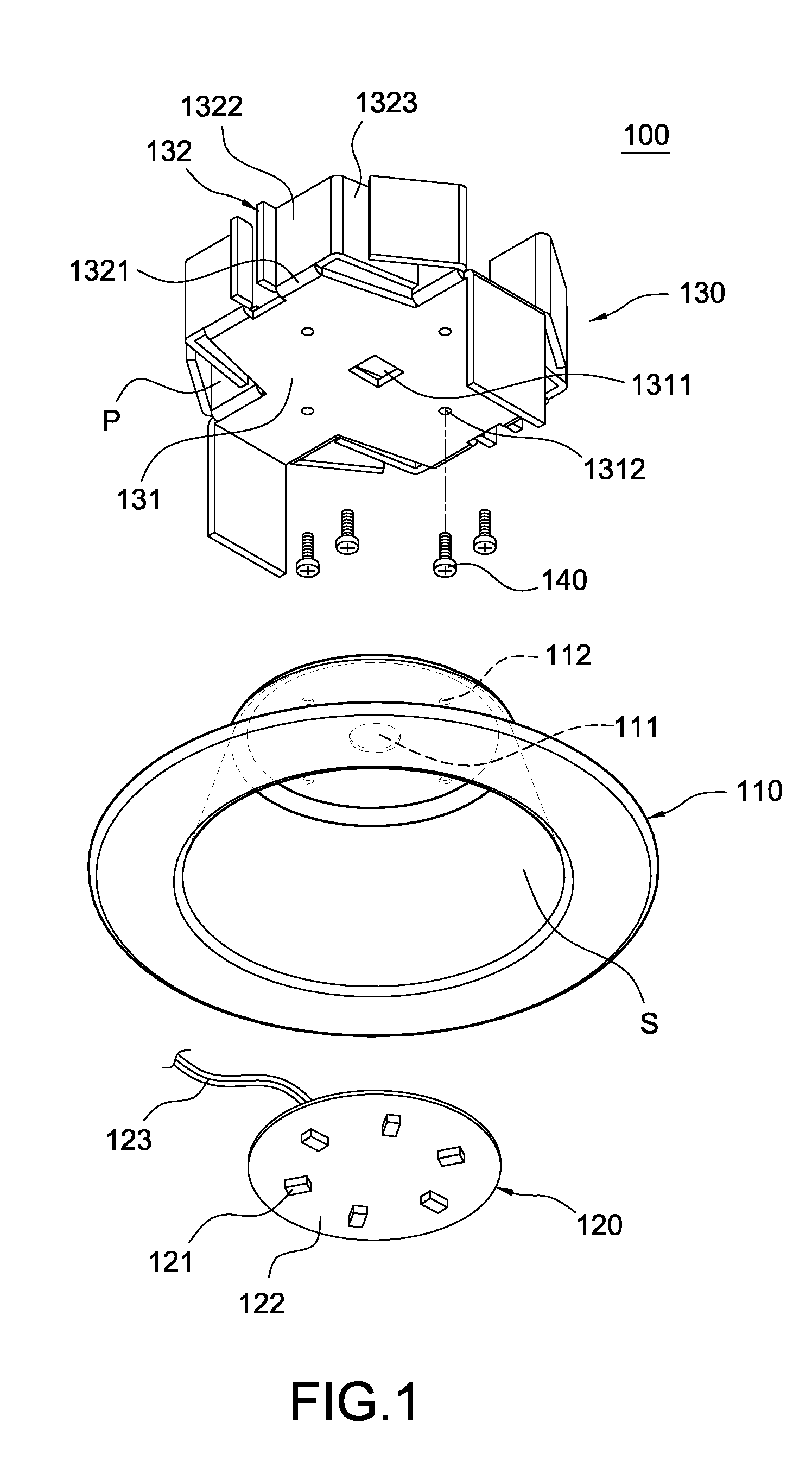
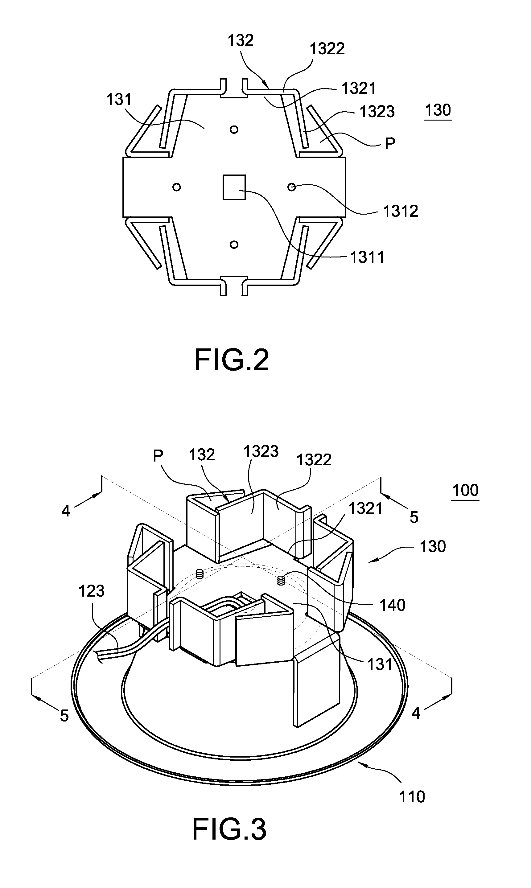
[0032]Please refer to FIGS. 1 to 5. The present invention provides a heat-dissipating module 130 and a lamp 100 having the heat-dissipating module 130.

[0033]As shown in FIG. 1, the lamp 100 of the present invention includes a casing 110, a light-emitting assembly 120 and the heat-dissipating module 130.

[0034]The casing 110 is made of metal material and has a hollow chamber S. The top surface of the casing 110 is provided with a wire-exiting hole 111 and a plurality of fixing holes 112. The light-emitting assembly 120 is provided in the hollow chamber S. The light-emitting assembly 120 includes a circuit board 121 and a plurality of LEDs 122 arranged on t...


PUM


Abstract

A heat-dissipating module includes a base plate and a plurality of fins. The base plate is made of sheet metal. The fins are formed by bending upwardly from the periphery of the base plate. Each of the fins has at least two bending sections. The region among the bending sections and the base plate is hollowed to form a plurality of airflow channels. By this structure, the airflow below the base plate can pass through the airflow channels to heat-exchange with the fins, thereby increasing the heat-dissipating effect. The present invention also relates to a lamp having the heat-dissipating module.

Description

BACKGROUND OF THE INVENTION[0001]1. Field of the Invention[0002]The present invention relates to a heat-dissipating module and a lamp having the same. More particularly, the present invention relates to a heat-dissipating module having vertical airflow channels and a lamp having such a heat-dissipating module.[0003]2. Description of Prior Art[0004]With the advancement of science and technology, light emitting diodes (LED) are widely used in various lamps to replace traditional incandescent bulbs because the LEDs have low electricity consumption and long lifetime. However, each LED generates heat when emitting light. If the thus-generated heat is not dissipated to the outside, the heat will be accumulated in the LED to raise its temperature. As a result, electronic components in the LED will suffer damage or even burn down.[0005]In order to solve the problem relating to the heat dissipation of the LEDs, the existing solution is to provide a heat-dissipating module made by aluminum ex...

Claims


Application Information

Patent Timeline
IPC IPC(8): F21S4/00F28F7/00F21V29/00
CPCF21V29/2231F21S8/026F21V29/78F21V29/773F21Y2101/02F21Y2115/10
Inventor LAI, CHYI-LANG
Owner CHICONY POWER TECH CO LTD
Why Eureka
Try Eureka