
Computer wake up circuit
a wake-up circuit and computer technology, applied in the field of computer wake-up circuits, can solve the problems of cost-intensive wake-up circuits, increased energy consumption,
- Summary
- Abstract
- Description
- Claims
- Application Information
AI Technical Summary
Benefits of technology
Problems solved by technology
Method used
Image

Examples
Embodiment Construction
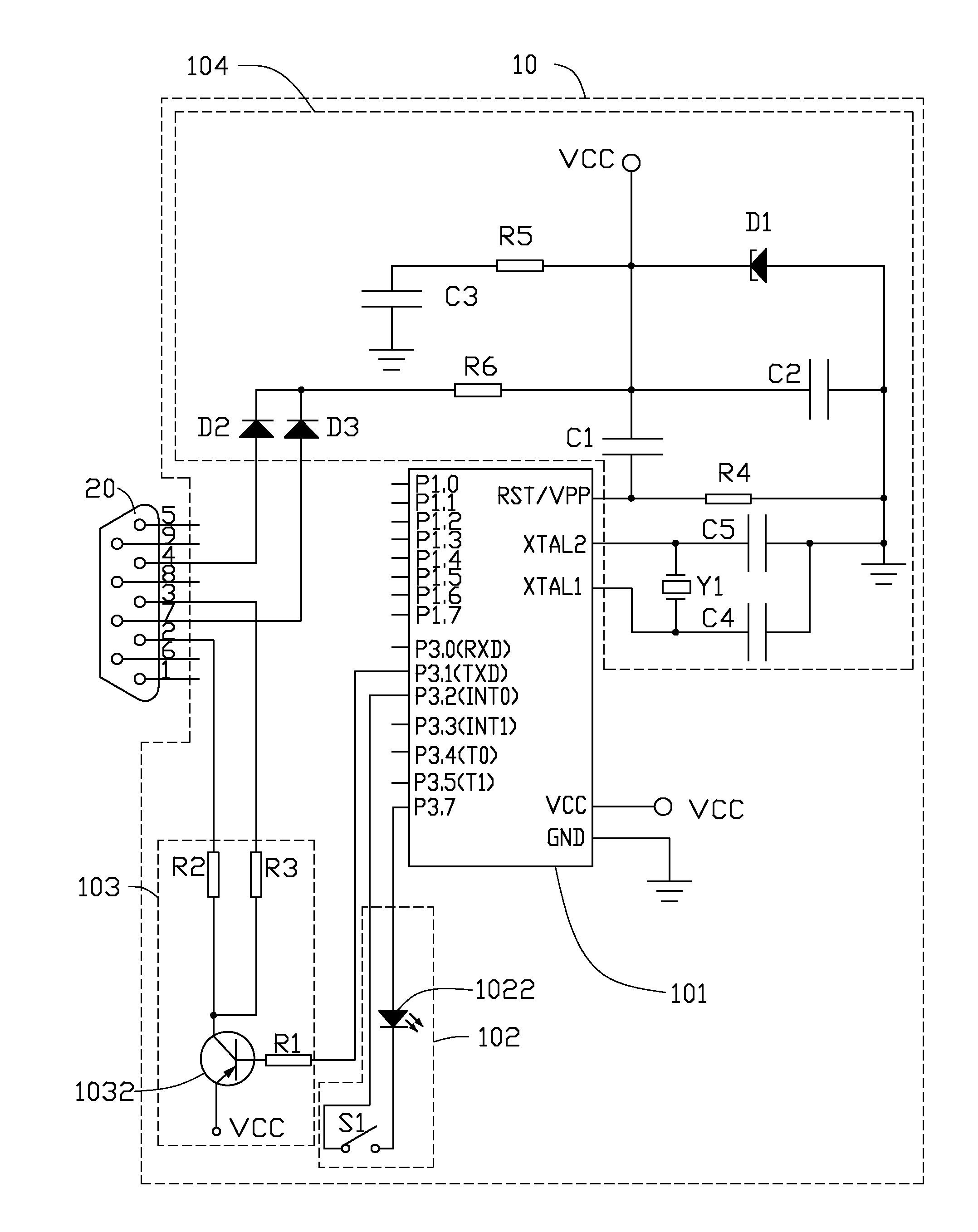
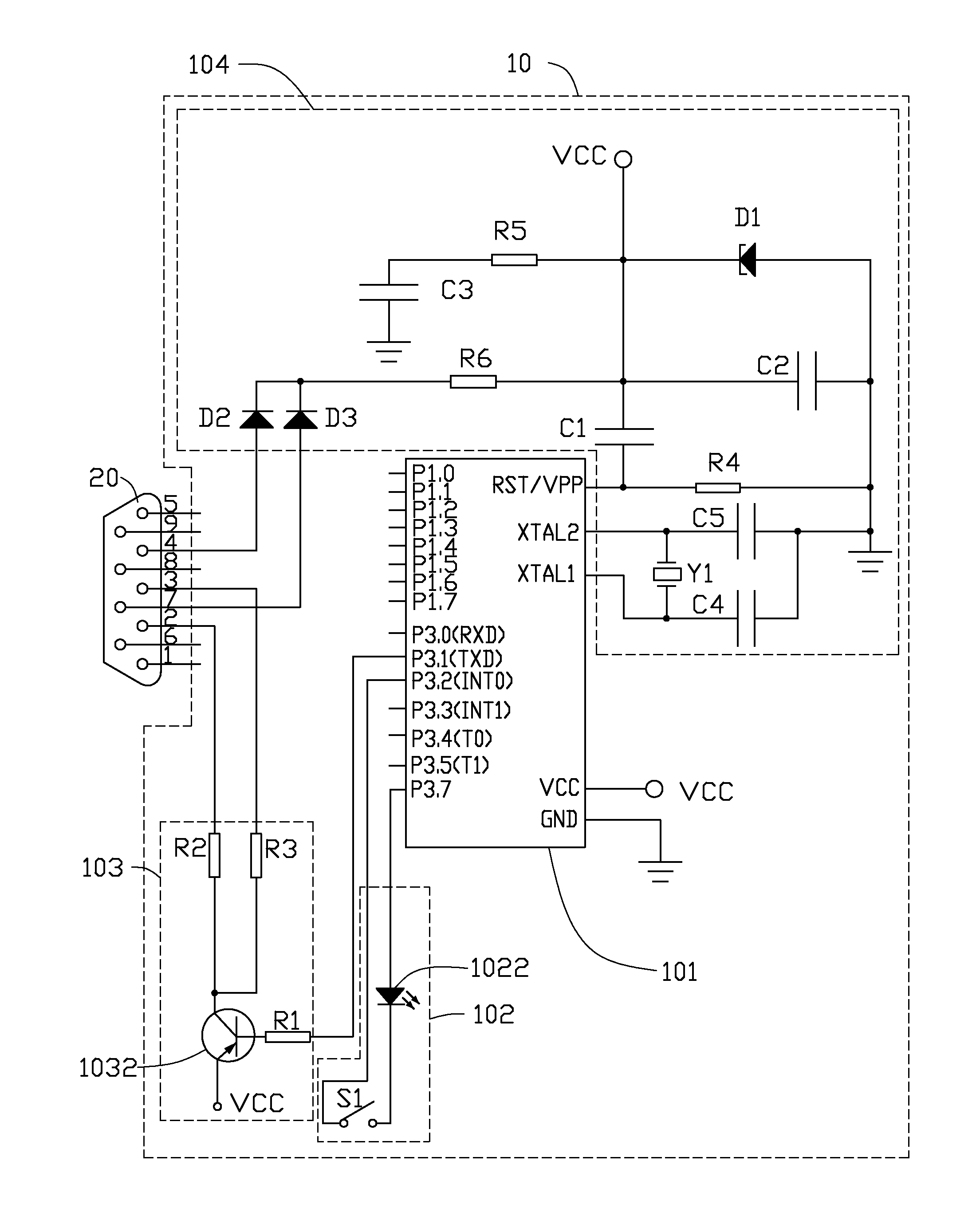
[0009]Referring to the drawing, a wake up circuit 10 for awaking a computer which is in a sleep state via the computer serial port 20, includes a microcontroller 101, switching circuit 102, an input circuit 103, and a protection circuit 104. The microcontroller 101 is one of the AT89 series. In this embodiment, AT89C2051 mono-chip is adopted as an example of the microcontroller 101.
[0010]The switching circuit 102 is coupled to the pins P3.2 (INT0) and P3.7 of the AT89C2051 microcontroller 101, for triggering the AT89C2051 microcontroller 101 to output a control signal. The switching circuit 102 includes a switch Si and a light source 1022. The switch S1 and the light source 1022 are electrically connected in series between the pins P3.2 (INT0) and P3.7 of the AT89C2051 microcontroller 101. In present embodiment, the light source 1022 is a light-emitting diode (LED).
[0011]The input circuit 103 includes a first resistance R1, a control switch 1032, a second resistance R2, and a third ...
PUM
 Abstract
Description
Claims
Application Information