Radio communication base station device and correlation setting method

a technology of radio communication and base station, applied in multiplex communication, orthogonal multiplex, wireless commuication services, etc., can solve the problems of data transmission efficiency reduction and communication resources available for data transmission, and achieve the effect of reducing the amount of communication resources used for srss

Active Publication Date: 2013-01-03
GK BRIDGE 1
View PDF5 Cites 9 Cited by
  • Summary
  • Abstract
  • Description
  • Claims
  • Application Information

AI Technical Summary

Benefits of technology

[0010]However, with the above-described conventional technique of performing transmission by assigning the SRS to the first LB in a subframe, the first LB in a subframe is more frequently used to transmit the SRS as the number of mobile stations in a cell increases. That is, the proportion of communication resources used to transmit SRSs increases as the number of mobile stations in the cell increases. Therefore, according to the above-described conventional technique, when the number of mobile stations within the cell increases, communication resources available for data transmission decrease, and, as a result, the data transmission efficiency is reduced.
[0011]An embodiment provides a radio communication base station apparatus and an association setting method capable of suppressing the amount of communication resources used for SRSs.
[0013]In an embodiment, the amount of communication resources used for SRSs may be reduced.

Problems solved by technology

Therefore, according to the above-described conventional technique, when the number of mobile stations within the cell increases, communication resources available for data transmission decrease, and, as a result, the data transmission efficiency is reduced.

Method used


Image

  • Radio communication base station device and correlation setting method
  • Radio communication base station device and correlation setting method
  • Radio communication base station device and correlation setting method

Examples


embodiment 1

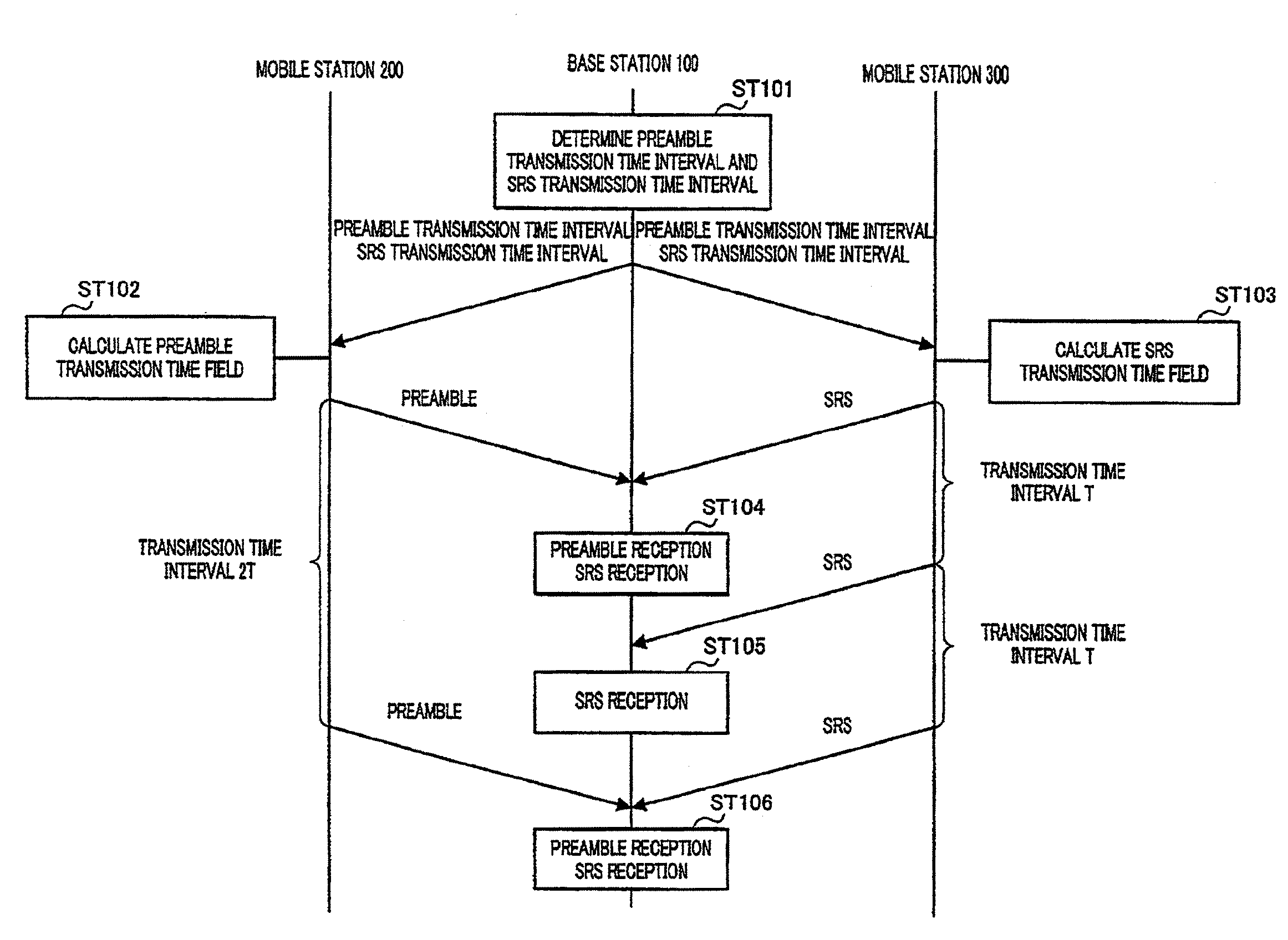
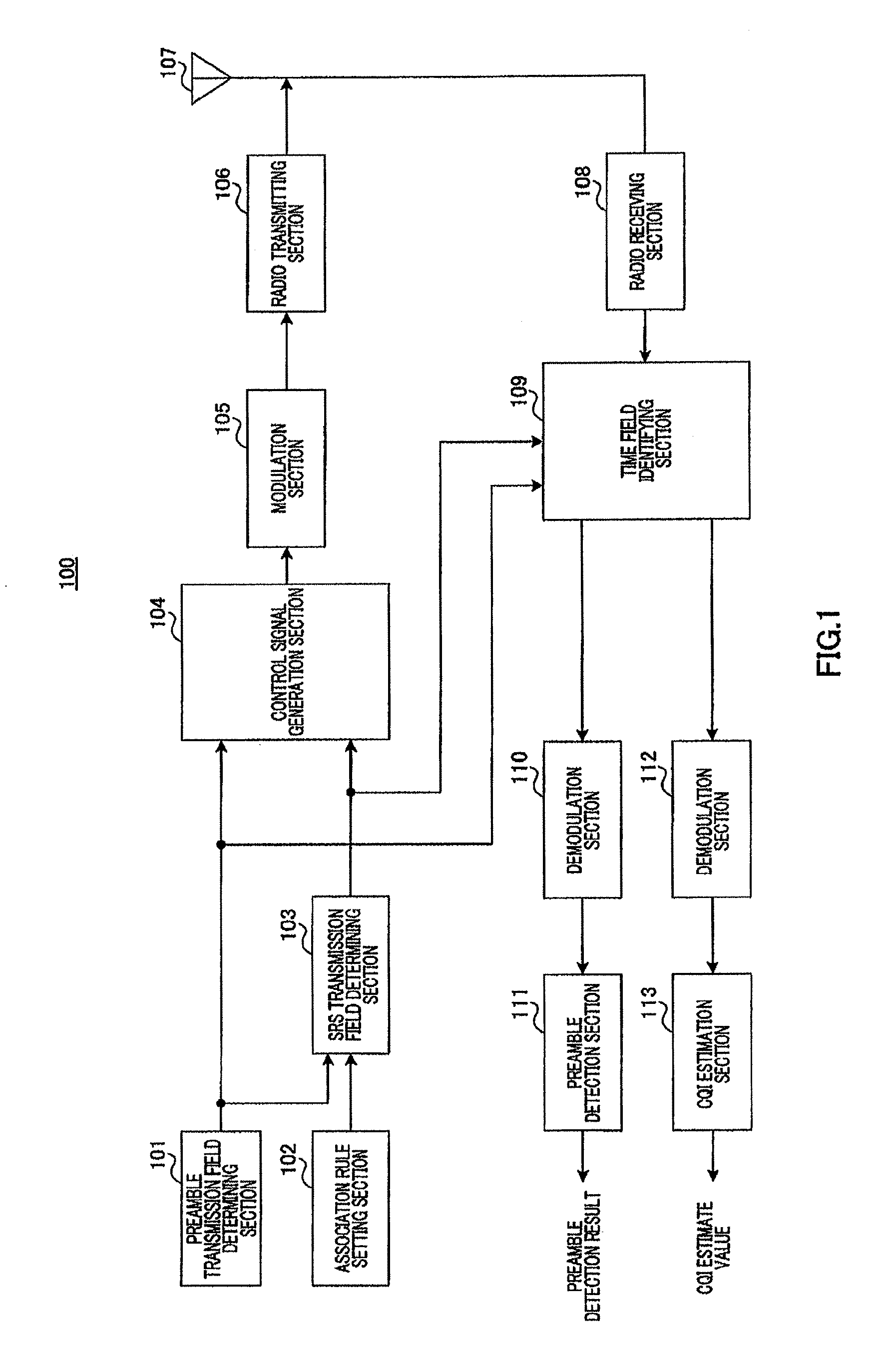
[0026]FIG. 1 shows a configuration of base station 100 according to the present embodiment. Base station 100 receives a preamble from mobile station 200 (FIG. 2) which will be described later and receives an SRS from mobile station 300 (FIG. 3) which will be described later.

[0027]Preamble transmission field determining section 101 determines the time interval of the transmission time field (subframe) in which the mobile station can transmit a preamble. Preamble transmission field determining section 101 then outputs the determined preamble transmission time interval to SRS transmission field determining section 103, control signal generation section 104 and time field identifying section 109.

[0028]Association rule setting section 102 sets rules for associating the transmission time intervals for the preamble and SRS. Association rule setting section 102 then outputs the association rules set, to SRS transmission field determining section 103. Details of the setting of the associatio...

embodiment 2

[0083]In the present embodiment, an SRS is arranged at the beginning of a preamble transmission time field.

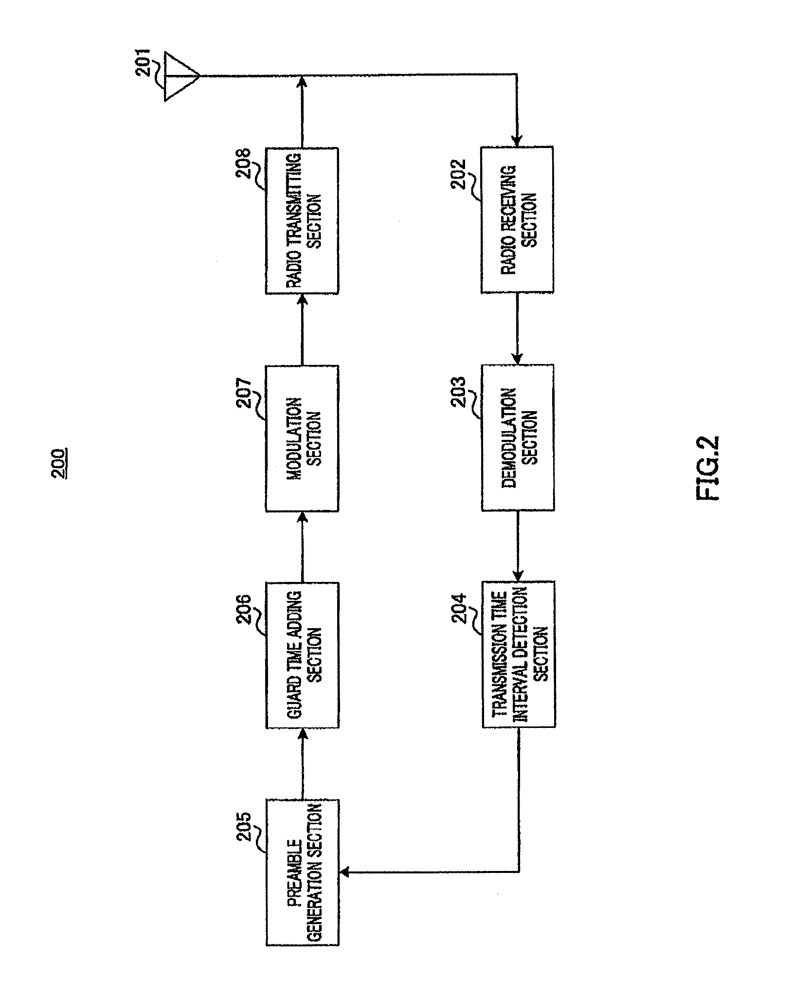
[0084]Guard time adding section 206 (FIG. 2) of mobile station 200 according to the present embodiment adds a guard time of the same time length as the SRS length before the preamble inputted from preamble generation section 205 and also adds a guard time of a time length corresponding to (1 subframe length—preamble length—SRS length) after the preamble.

[0085]On the other hand, when arranging an SRS in a preamble transmission time field (subframe), arrangement section 307 (FIG. 3) of mobile station 300 according to the present embodiment arranges the SRS at the beginning of the preamble transmission time field (subframe).

[0086]This will be explained more specifically below. Here, suppose the preamble transmission time field is formed with 14 LBs and the time length of the SRS is 1 LB as with Embodiment 1.

[0087]Therefore, as shown in FIG. 7, arrangement section 307 arranges the ...

embodiment 3

[0090]A case has been described with Embodiment 1 where the preamble and SRS transmission time fields are made to match each other, but a case will be explained now with the present embodiment where the preamble and SRS transmission time fields and the transmission band are made to match each other.

[0091]This will be explained more specifically below. In the following explanations, suppose that preambles and SRSs are transmitted using frequency hopping.

[0092]FIG. 8 shows a configuration of base station 400 according to the present embodiment. In FIG. 8, the same components as those in Embodiment 1 (FIG. 1) will be assigned the same reference numerals, and explanations thereof will be omitted.

[0093]Preamble transmission field determining section 401 of base station 400 according to the present embodiment determines a time interval (subframe) in which each mobile station can transmit the preamble and a transmission band in which the preamble can be transmitted.

[0094]Association rule s...


PUM


Abstract

Provided is a radio communication base station device which can suppress a use amount of an SRS communication resource. In this device, a correlation rule setting unit (102) sets a rule for correlating a preamble with an SRS transmission time interval so that the preamble transmission time band and the SRS transmission time band are in the same transmission time band. An SRS transmission band decision unit (103) decides a time interval of a transmission time band which can transmit the SRS according to the preamble transmission time interval inputted from a preamble transmission band decision unit (101) and the correlation rule setting unit (102).

Description

TECHNICAL FIELD[0001]The present disclosure relates to a radio communication base station apparatus and an association setting method.BACKGROUND ART[0002]The 3GPP RAN LTE (Long Term Evolution) is currently studying transmission of SRSs (Sounding Reference Signals) for channel quality estimation (CQI (Channel Quality Indicator) estimation) for frequency scheduling, reception timing detection and transmission power control on uplink from a radio communication mobile station apparatus (hereinafter abbreviated as a “mobile station”) to a radio communication base station apparatus (hereinafter abbreviated as a “base station”) (e.g. see Non-Patent Document 1).[0003]According to the 3GPP RAN LTE, for example, an SRS is formed with one LB (Long Block) and the time length of the SRS is 71.4 μs including the CP (Cyclic Prefix) and the reference signal. Furthermore, the mobile station transmits SRSs periodically (e.g. at 1-subframe intervals =at 1 ms intervals), according to command from the b...

Claims


Application Information

Patent Timeline
Patent Type & Authority Applications(United States)
IPC IPC(8): H04W74/08H04J11/00H04W72/04H04W72/12
CPCH04L5/0007H04W74/0833H04L27/2613H04L5/0051H04L27/26134H04L5/0048H04L27/2607H04L5/0053H04W74/0816H04W74/00H04W76/14H04W40/246H04L5/0082H04W72/0446
Inventor IWAI, TAKASHIIMAMURA, DAICHITAKATA, TOMOFUMIMATSUMOTO, ATSUSHIOGAWA, YOSHIHIKOFUTAGI, SADAKI
Owner GK BRIDGE 1
Why Eureka
Try Eureka