Flying Vehicle

a technology for flying vehicles and rotors, applied in the field of convertible vehicles, can solve the problems of frustration, increasing congestion on roads, and only having very limited mobility of helicopters on the ground, and achieve the effects of enabling independent control of individual rotors, improving the performance and efficiency of rotors/propellers, and variable control of vehicles

Active Publication Date: 2013-03-21
RADU BOGDAN
View PDF29 Cites 114 Cited by
  • Summary
  • Abstract
  • Description
  • Claims
  • Application Information

AI Technical Summary

Benefits of technology

[0023]An advantage of the invention is that it enables independent control of the individual rotors without complicated mechanical force-distribution couplings.
[0024]Another advantage of the invention is that the rotor / propeller can be adapted to current flight conditions or the current airflow speed in the rotor plane, thus improving the performance and efficiency of the rotor / propeller.
[0025]Yet another advantage is that the invention enables usage of the side unpacked rotors for an easy flight configuration and enables improved, variable control of the vehicle.
[0026]The invention enables the main rotor planes to be fixed in forward flight so as to generate lift, with the rotors / propellers having to generate only thrust.
[0027]Because of its brushless motor configuration, in comparison with frequency-controlled three-phase motors, the invention provides high torque at both low and high rotational speeds. This results in a long service life without excessively high energy storage weights due to the high specific electrical energy.
[0028]Another object of the present invention is to provide a rapid configuration change between the land / water and air operability of the vehicle.

Problems solved by technology

Yet, despite having the capability of six degrees of freedom for moving along or rotating around all three axes during flight configuration, helicopters on the ground usually have only very limited mobility, or none at all.
The roads are becoming more and more congested due to the increased number of vehicles.
Roads congestion creates frustration to those trapped in them, wasting their time.

Method used


Image

  • Flying Vehicle
  • Flying Vehicle
  • Flying Vehicle

Examples


Embodiment Construction

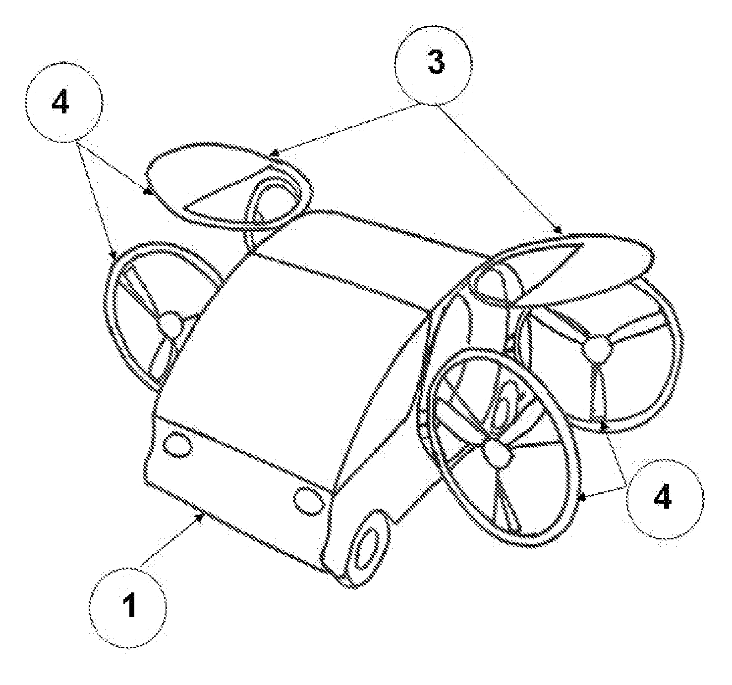
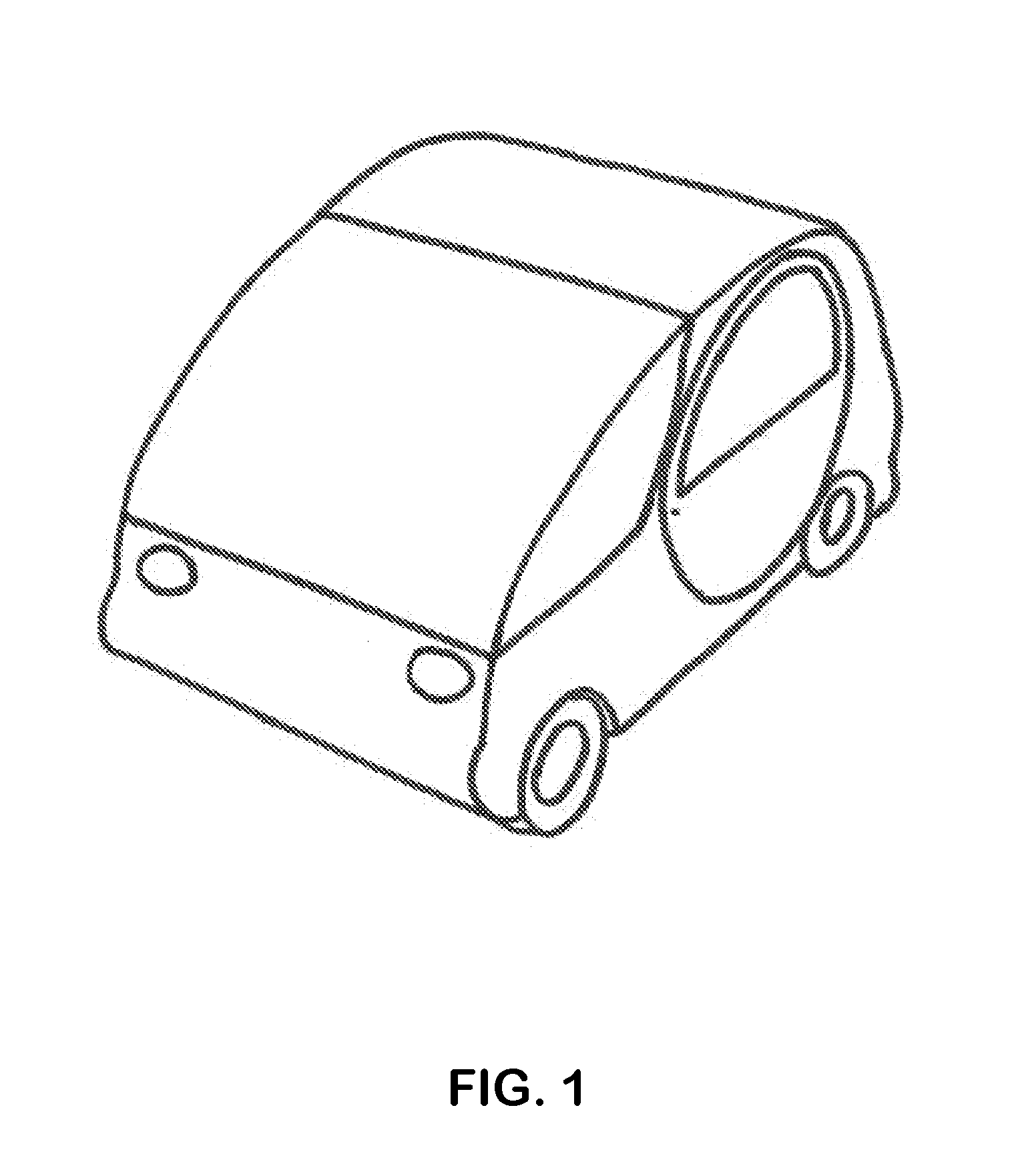
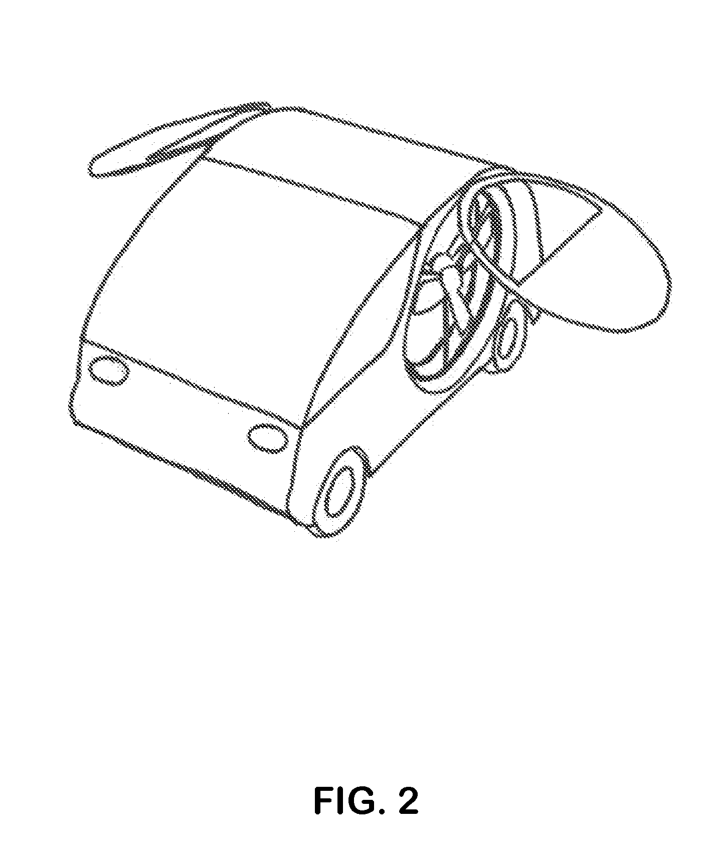
[0073]Referring to the above figures, the present invention is embodied in a flying vehicle that operates in the manner of a Vertical Take-Off and Landing (VTOL) / Short Take-off and Landing (STOL) or a helicopter type aircraft but is sized and designed to be similar with a personal land vehicle. The vehicle comprises a main body that is in the shape of a land car / amphibious vehicle and which has a front end 1, a rear end 2 and side storage compartment cover doors 3 which cover the rotors / propellers 4 (FIG. 11). The rotors / propellers can open and rotate independently with the mechanism 5 around the transverse axles 7 (FIG. 12). The main body further includes side rotors storage compartments with the intent of storing the rotor and their blades during the land / water operation of the vehicle. The main body further includes the side storage compartment cover doors that in the closed configuration cover the rotors and their blades in of the vehicle land configuration and in the same close...


PUM


Abstract

A vehicle has a roadable configuration similar to an automobile in which multiple rotors are stowed within the vehicle, and a flying configuration in which the rotors are deployed from the vehicle, allowing it to fly like a VTOL / STOL aircraft or a helicopter.

Description

[0001]This application claims benefit of provisional patent application 61 / 535,448, filed Sep. 16, 2011.BACKGROUND OF THE INVENTION[0002]This invention relates generally to a convertible vehicle which can drive on the ground, move on water, and fly, with minor configuration changes.[0003]Some aircraft are known which, like the V22 Osprey aircraft configuration, have rotors that can tilt, allowing aircraft vertical take-off and landing.[0004]Helicopters' rotors can be tilted within certain limits, which is absolutely essential for their control. Yet, despite having the capability of six degrees of freedom for moving along or rotating around all three axes during flight configuration, helicopters on the ground usually have only very limited mobility, or none at all.[0005]Roadways are generally used by people driving land vehicles. The roads are becoming more and more congested due to the increased number of vehicles. Roads congestion creates frustration to those trapped in them, wasti...

Claims


Application Information

Patent Timeline
Patent Type & Authority Applications(United States)
IPC IPC(8): B60F5/02
CPCB60F5/02
Inventor RADU, BOGDAN
Owner RADU BOGDAN
Why Eureka
Try Eureka