Scroll compressor

Pending Publication Date: 2022-09-22
HANON SYST
View PDF0 Cites 0 Cited by
  • Summary
  • Abstract
  • Description
  • Claims
  • Application Information

AI Technical Summary

Problems solved by technology

However, in the conventional scroll compressor, an amount of refrigerant discharged from the compression c

Method used


Image

  • Scroll compressor
  • Scroll compressor
  • Scroll compressor

Examples


Embodiment Construction

[0057]Hereinafter, a scroll compressor according to the present disclosure will be described in detail with reference to the accompanying drawings.

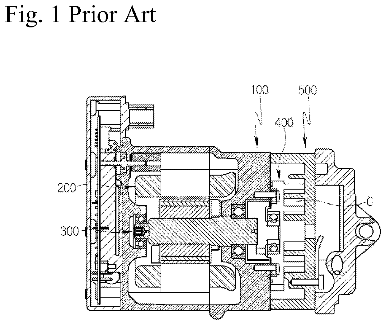
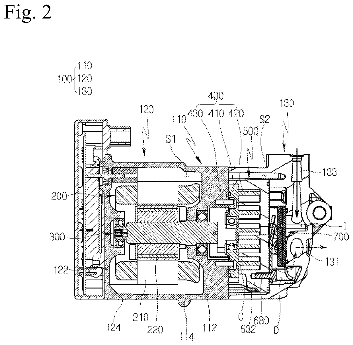
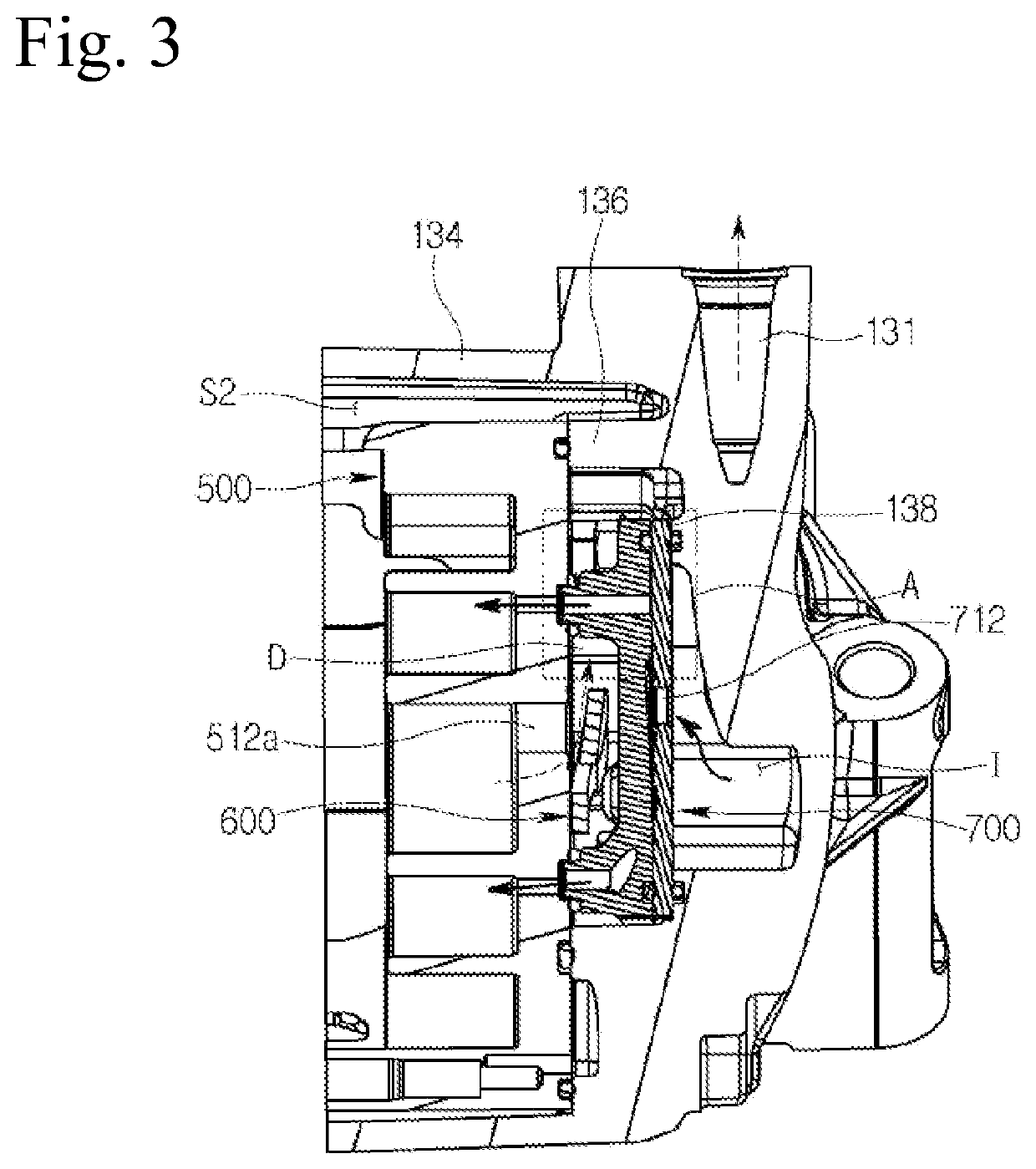
[0058]FIG. 2 is a cross-sectional view showing a scroll compressor according to an embodiment of the present disclosure, FIG. 3 is a cross-sectional view showing a rear housing side of the scroll compressor of FIG. 2 from another direction, FIG. 4 is an enlarged cross-sectional view of part A of FIG. 3, FIG. 5 is a front view showing a rear housing of the scroll compressor of FIG. 2, FIG. 6 is a rear view of FIG. 5, FIG. 7 is a perspective view showing a part of the rear housing cut away as a perspective view of FIG. 6, FIG. 8 is an exploded perspective view showing parts accommodated in the rear housing of FIG. 7, FIG. 9 is an exploded perspective view showing an injection valve assembly of the parts of FIG. 8, FIG. 10 is a perspective view showing a rear surface of a cover plate of the injection valve assembly of FIG. 9, FIG. 11 is a pe...


PUM


Abstract

A scroll compressor includes a housing; a motor provided in the housing; a rotating shaft rotated by the motor; an orbital scroll orbital moved by the rotating shaft; a fixed scroll forming a compression chamber together with the orbital scroll; an injection flow path guiding an intermediate pressure refrigerant from an outside of the housing to the compression chamber; and an injection valve assembly opening and closing the injection flow path, wherein the injection valve assembly includes a cover plate having an inlet through which the intermediate pressure refrigerant is introduced, an injection valve opening and closing the inlet, and a valve plate having an outlet guiding the refrigerant that has passed through the injection valve toward the compression chamber. Thereby, an amount of refrigerant discharged from the compression chamber is increased, and thus the performance and efficiency of the compressor may be improved.

Description

CROSS-REFERENCE TO RELATED PATENT APPLICATIONS[0001]This patent application is a United States nation phase patent application based on PCT / KR2020 / 008633 filed on Jul. 2, 2020, which claims the benefit of Korean Patent Application No. 10 2019 0089759 filed on Jul. 24, 2019, the entire disclosures of which are hereby incorporated herein by reference.TECHNICAL FIELD[0002]The present disclosure relates to a scroll compressor, and more particularly, to a scroll compressor capable of compressing a refrigerant with a fixed scroll and an orbital scroll.BACKGROUND ART[0003]In general, an air conditioning device (A / C) for heating and cooling an interior is installed in a vehicle. The air conditioning device is a component of a cooling system, and includes a compressor compressing a low-temperature and low-pressure gaseous refrigerant introduced from an evaporator into a high-temperature and high-pressure gaseous refrigerant and sending it to a condenser.[0004]The compressor includes a recipr...

Claims


Application Information

Patent Timeline
IPC IPC(8): F04C29/12F04C18/02
CPCF04C29/12F04C18/0215F04C18/02F04C29/042F04C18/0261F04C2250/102F04C29/124F04C2240/30F04C2210/26F04C2240/20F05B2240/20F05B2210/14
Inventor LEE, KYUNG JAESEO, JEONG KI
Owner HANON SYST
Why Eureka
Try Eureka