
Urea SCR catalyst and manufacturing method for the same

a technology of selective catalytic reduction and catalyst, which is applied in the direction of physical/chemical process catalyst, metal/metal-oxide/metal-hydroxide catalyst, and separation process, etc., can solve the problems of secondary toxic materials, poor durability at high temperature, and secondary pollution, and achieve the effect of increasing the active surface area, performance and efficiency of the catalys

Inactive Publication Date: 2009-11-26
HYUNDAI MOTOR CO LTD
View PDF2 Cites 3 Cited by
  • Summary
  • Abstract
  • Description
  • Claims
  • Application Information

AI Technical Summary

Benefits of technology

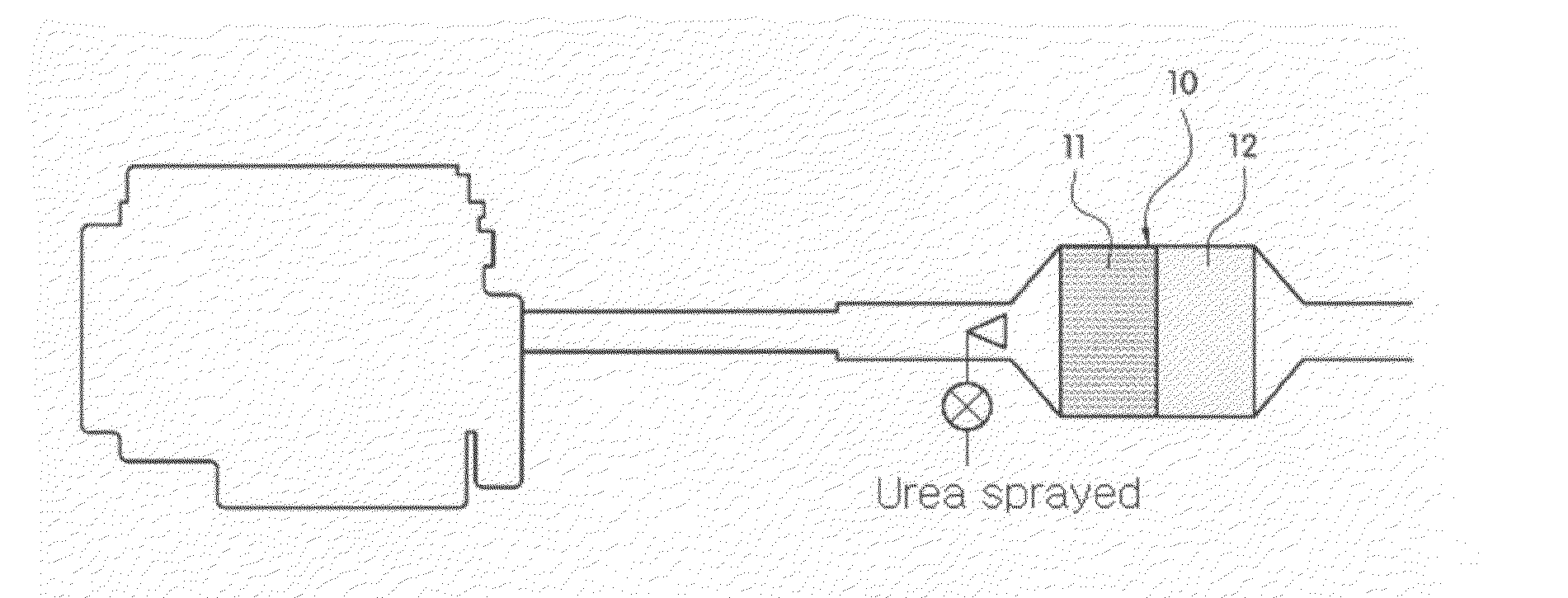
[0010]In one aspect, the present invention is directed to a selective reduction catalyst, where half of the catalyst (an inlet) is coated with Mn / TiO2 and another half of the catalyst (an outlet) is coated with Fe-zeolite / ZSM along the longitudinal direction and a washcoat layer is prepared by adding cerium carbonate, thereby forming pores caused by decomposition during calcinations in the washcoat layer and increasing active surface area and performance and efficiency of the catalyst. The invention also features methods of preparation of the selective reduction catalyst as described in the aforementioned aspect.
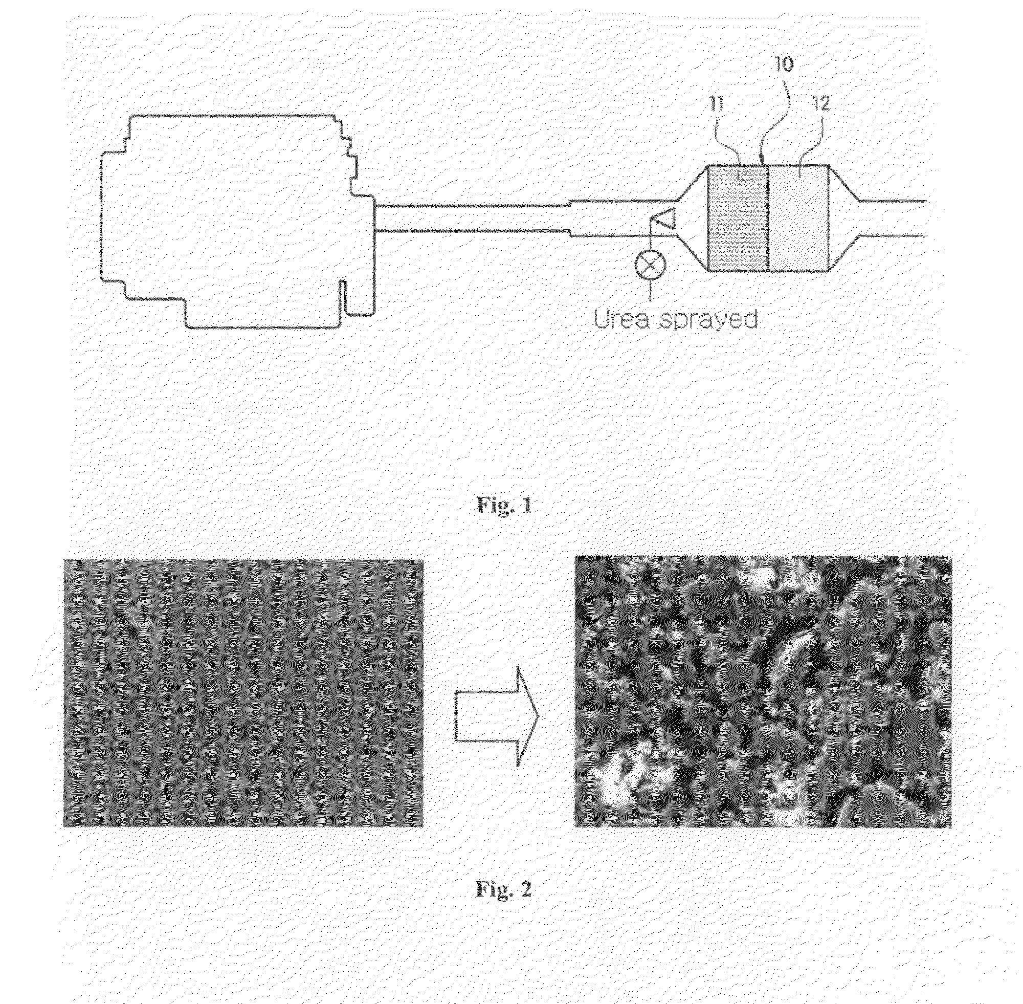
[0019]In other embodiments, according to a selective reduction catalyst and its preparation method of the present invention as described herein, a washcoat prepared by using cerium carbonate before coating steps in catalyst structure, where both Mn / TiO2 and Fe-zeolite / ZSM are applied, produces pores caused by the decomposition during calcination in the washcoat, thereby increasing active surface area and improving the performance and efficiency of the catalyst.

Problems solved by technology

However, in the conventional methods there is secondary pollution due to unreacted NH3, and there are safety concerns related to the NH3 tank and the necessity of a large-sized facility for reducing NOx because of the relatively low space velocity (5,000-10,000 hr−1) of the V2O5 / TiO2 catalyst.
However, although V2O5 catalytic agent has excellent activity at low temperature, it has poor durability at high temperature, and also produces secondary toxic materials.
Recent attempts to use Mn and Ce among metal oxides have not been successful.

Method used


Image

  • Urea SCR catalyst and manufacturing method for the same
  • Urea SCR catalyst and manufacturing method for the same

Examples


examples

[0042]The following examples illustrate the present invention and are not intended to limit the same.

example

[0043]In one example, to prepare a first catalyst slurry, Mn / TiO2(11) superior in low-temperature activity is mixed with alumina, for example in a mixing ratio of 1:10-2:8 (50 g), and added with a mixture of 5 g of cerium carbonate (CeCO3), 27.0 g of acetic acid and 375 mL of water, followed by the adjustment of pH to 4.2 by using acetic acid.

[0044]Catalyst slurry (viscosity 200-300 cpsi, solid content: 30-40%) was obtained according to a ball mill method by milling the slurry in such a manner that particles with size of less than 7 μm may amount to 94%. The aforementioned ranges are preferred considering durability, thermal resistance and initial performance of catalyst.

[0045]To prepare a second catalyst slurry, beta zeolite and ZSM-5 are suitably mixed in a mixing ratio of 1:1 (50 g), and added with a mixture of 5 g of cerium carbonate (CeCO3), 27.0 g of acetic acid and 375 mL of water, followed by the adjustment of pH to 4.2 by using acetic acid.

[0046]Preferably, the ratio of zeo...


PUM

PropertyMeasurementUnit
Temperatureaaaaaaaaaa
Surface areaaaaaaaaaaa

Abstract

The present invention features a selective reduction catalyst, where half of the catalyst (an inlet) is coated with Mn / TiO2 and another half of the catalyst (an outlet) is coated with Fe-zeolite / ZSM along a substantially longitudinal direction and a washcoat layer is prepared by adding cerium carbonate, thereby forming pores caused by decomposition during calcinations in the washcoat layer and increasing active surface area and performance and efficiency of the catalyst. Also featured are methods of preparation of the selective reduction catalyst.

Description

CROSS-REFERENCE TO RELATED APPLICATION[0001]This application claims under 35 U.S.C. §119(a) the benefit of Korean Patent Application No. 10-20087-0047455 filed May 22, 2008, the entire contents of which are incorporated herein by reference.BACKGROUND[0002](a) Technical Field[0003]The present invention relates to a catalyst for selective catalytic reduction preparation methods, and, more particularly to a catalyst for selective catalytic reduction, where Mn—TiO2 and Fe-zeolite are coated with a catalytic agent, thereby improving the activity of urea in removing nitrogen oxides both at low and high temperature, and to its preparation method.[0004](b) Background Art[0005]The selective catalytic reduction (SCR) method has been described in the reduction of NOx discharge. In the SCR method, a catalyst, where V2O5 is coated onto TiO2, is used in combination with ammonia (NH3) as a reducing agent. It has been reported that reduction yield can be up to 80% when the reaction is performed at ...

Claims


Application Information

Patent Timeline
IPC IPC(8): B01J29/064B05D5/00B05D1/36B05D3/02
CPCB01D53/9418B01J37/0246B01D2251/2067B01D2255/2065B01D2255/20707B01D2255/2073B01D2255/20738B01D2255/2092B01D2255/502B01D2255/504B01D2258/012B01J21/063B01J23/34B01J29/072B01J29/40B01J29/46B01J29/7007B01J29/80B01J35/0006B01J37/0036B01J37/0215B01D53/9477B01J35/19B01J21/06B01J29/064
Inventor YEO, GWON KOO
Owner HYUNDAI MOTOR CO LTD
Learn More