Power generation unit, electronic apparatus, transportation device, and method of controlling power generation unit

a power generation unit and electronic equipment technology, applied in piezoelectric/electrostrictive/magnetostrictive devices, piezoelectric/electrostriction/magnetostriction machines, electrical apparatus, etc., can solve the problems of limited voltage and difficulty in sufficiently miniaturizing the power generation unit, and achieve the effect of efficiently providing electricity and generating electricity

Inactive Publication Date: 2013-04-04
SEIKO EPSON CORP
View PDF4 Cites 15 Cited by
  • Summary
  • Abstract
  • Description
  • Claims
  • Application Information

AI Technical Summary

Benefits of technology

[0044]According to these aspects of the invention, since it is possible to incorporate the power generation unit in a remote controller or a portable electronic apparatus instead of a battery, the power can be generated due to the transportation of the electronic apparatus, and in addition, by using the power generation unit according to the application example of the invention in a transportation device such as a vehicle or a electric train, it is also possible to generate electricity by the vibration due to the transportation, and to efficiently supply the electricity to the equipment provided to the transportation device.

Problems solved by technology

However, in the proposed technology according to the related art, there arises a problem that the obtainable voltage is limited up to the voltage generated by the electrical polarization of the piezoelectric material.
Therefore, in most cases, an additional step-up circuit is required, and there arises a problem that it is difficult to sufficiently miniaturize the power generation unit.

Method used


Image

  • Power generation unit, electronic apparatus, transportation device, and method of controlling power generation unit
  • Power generation unit, electronic apparatus, transportation device, and method of controlling power generation unit
  • Power generation unit, electronic apparatus, transportation device, and method of controlling power generation unit

Examples


first embodiment

A. FIRST EMBODIMENT

A-1. Structure of Power Generation Unit

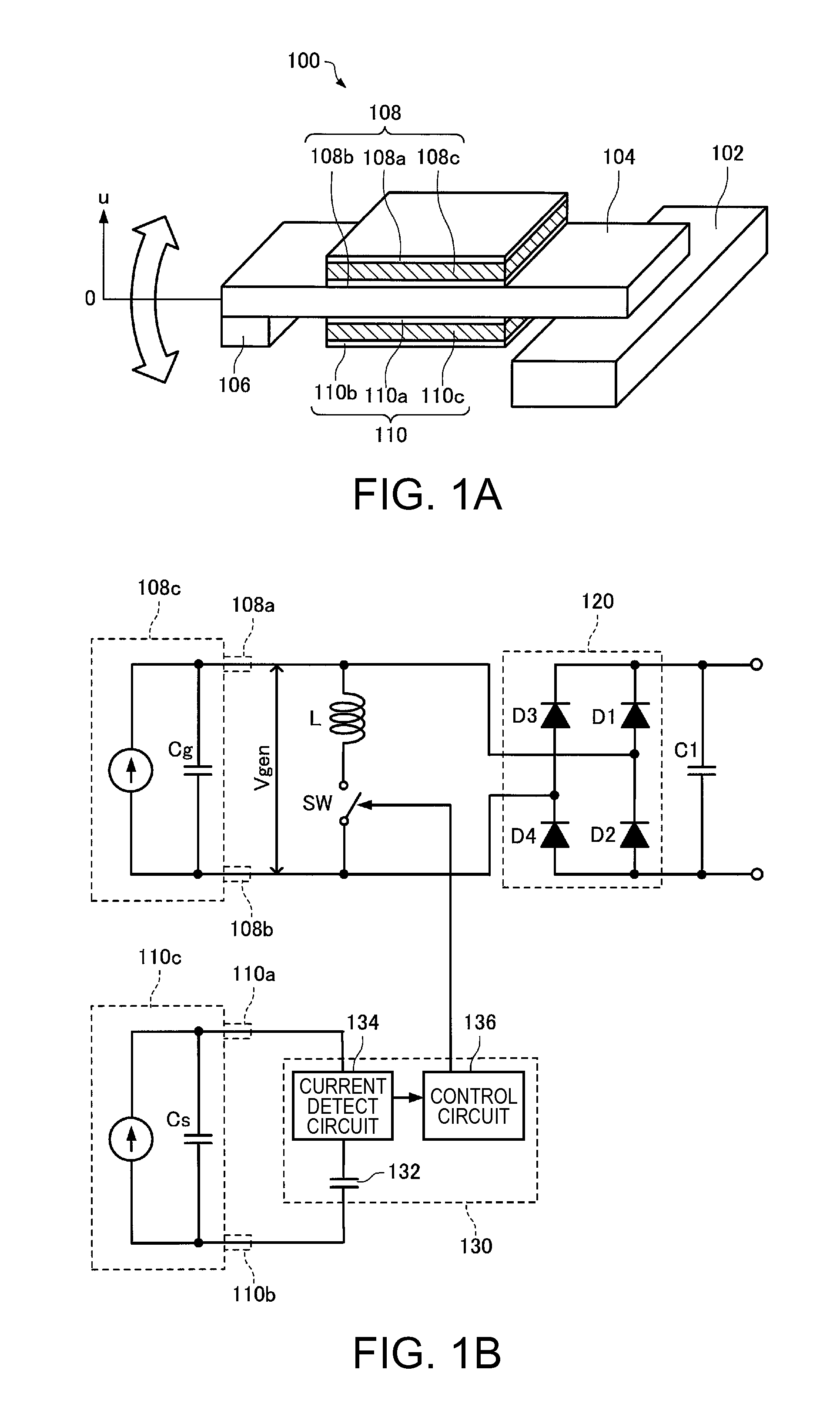
[0083]FIGS. 1A and 1B are explanatory diagrams showing a structure of a power generation unit 100 according to the present embodiment. FIG. 1A shows a mechanical structure of the power generation unit 100, and FIG. 1B shows an electrical structure thereof. The mechanical structure of the power generation unit 100 according to the present example is formed as a cantilever structure in which the beam 104 having a mass 106 disposed at the tip thereof is fixed to a base 102 on the base end side thereof, and the beam 104 can deform while switching the deformation direction. The base 102 is preferably fixed inside the power generation unit 100. A piezoelectric device 108 and a piezoelectric device 110 are disposed on the surface of the beam 104. The piezoelectric device 108 is configured including a piezoelectric element 108c formed of a piezoelectric material such as lead zirconium titanate (PZT), and a first electrode (an upper e...

second embodiment

B. SECOND EMBODIMENT

[0142]In the explanation of the power generation unit 100 according to the first embodiment described above, it is assumed that a single controlling piezoelectric device 110 is disposed. However, it is not necessarily required to provide the single controlling piezoelectric device 110, but a plurality of such controlling piezoelectric devices can also be provided. Hereinafter, a second embodiment with such a configuration will be explained. The constituents substantially the same as those of the first embodiment will also be attached with the same reference numerals in the second embodiment, and the detailed explanation therefor will be omitted.

[0143]FIGS. 13A through 13C are explanatory diagrams showing the power generation unit 100 according to the second embodiment provided with the plurality of controlling piezoelectric devices. FIG. 13A is a plan view thereof viewed from one surface of the beam 104. FIG. 13B is a plan view thereof viewed from the other surfa...

third embodiment

C. THIRD EMBODIMENT

[0150]FIG. 14 is a circuit diagram showing the electrical structure of the power generation unit 100 according to a third embodiment. The mechanical structure of the power generation unit 100 according to the third embodiment is the same as the structure shown in FIG. 1A. The constituents substantially the same as those of the first embodiment will also be attached with the same reference numerals in the third embodiment, and the detailed explanation therefor will be omitted.

[0151]In the power generation unit 100 according to the third embodiment, the controlling piezoelectric device 110 is also provided in addition to the power-generating piezoelectric device 108, and the voltage generated in the piezoelectric device 110 is detected to thereby control the switch SW.

[0152]The power generation unit 100 according to the third embodiment includes a control section 130a. The control section 130a performs the ON / OFF control of the switch SW. Specifically, the control s...


PUM


Abstract

A power generation unit includes a deforming member (a beam) adapted to deform while switching a deformation direction, a first piezoelectric device provided to the deforming member (the beam), a second piezoelectric device provided to the deforming member (the beam), an inductor electrically connected to the first piezoelectric device, a switch disposed between the first piezoelectric device and the inductor, and a control section adapted to detect a voltage generated in the second piezoelectric device, and if the voltage detected has a level one of equal to and higher than a predetermined level, electrically connect the first piezoelectric device and the inductor to each other using the switch.

Description

BACKGROUND[0001]1. Technical Field[0002]The present invention relates to a power generation unit, an electronic apparatus, a transportation device, and a method of controlling the power generation unit.[0003]2. Related Art[0004]When a piezoelectric material such as lead zirconium titanate (PZT), quartz crystal (SiO2), or zinc oxide (ZnO) is deformed in response to an external force, electrical polarization is induced inside the material, and positive and negative charges appear on the surfaces. Such a phenomenon is called a so-called piezoelectric effect. There has been proposed an electrical power generation method of vibrating a cantilever to thereby make a weight repeatedly act on the piezoelectric material, and thus taking out the charge generated on the surface of the piezoelectric material as electricity using such a characteristic provided to the piezoelectric material.[0005]For example, by vibrating a metal cantilever having a mass disposed at the tip and a thin plate made o...

Claims


Application Information

Patent Timeline
Patent Type & Authority Applications(United States)
IPC IPC(8): H02N2/00
CPCH02N2/181H01L41/1136H10N30/306
Inventor TABATA, KUNIOHIRABAYASHI, ATSUYAOSHIMA, ATSUSHIYOSHINO, HIROYUKIIDE, NORITAKA
Owner SEIKO EPSON CORP
Why Eureka
Try Eureka