

Electric blower and vacuum cleaner comprising same
a technology of electric blower and vacuum cleaner, which is applied in the direction of carpet cleaners, liquid fuel engines, bowling games, etc., can solve the problems of reducing the suctioning power increasing the loss attributable to the increase in slippage and backflow of the air at the trailing edges, and worsening the operability. , to achieve the effect of reducing the operating noise of the vacuum cleaner, reducing noise, and strong suctioning force without increasing the size and weigh
- Summary
- Abstract
- Description
- Claims
- Application Information
AI Technical Summary
Benefits of technology
Problems solved by technology
Method used
Image

Examples
first exemplary embodiment
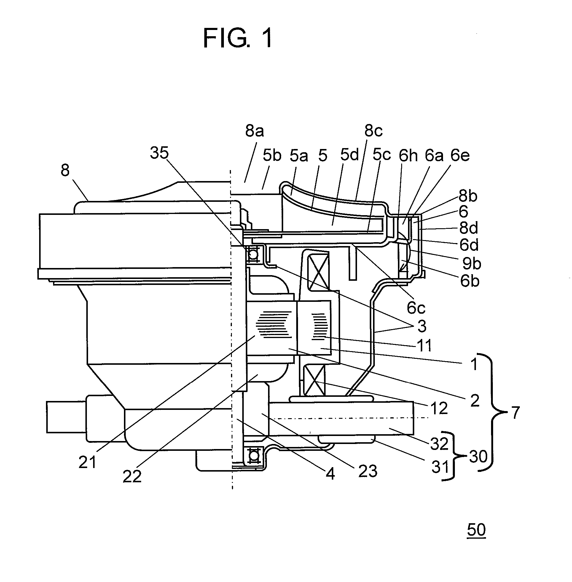
[0033]Described now pertains to electric blower 50 for use in an electric apparatus according to the first embodiment of this invention.
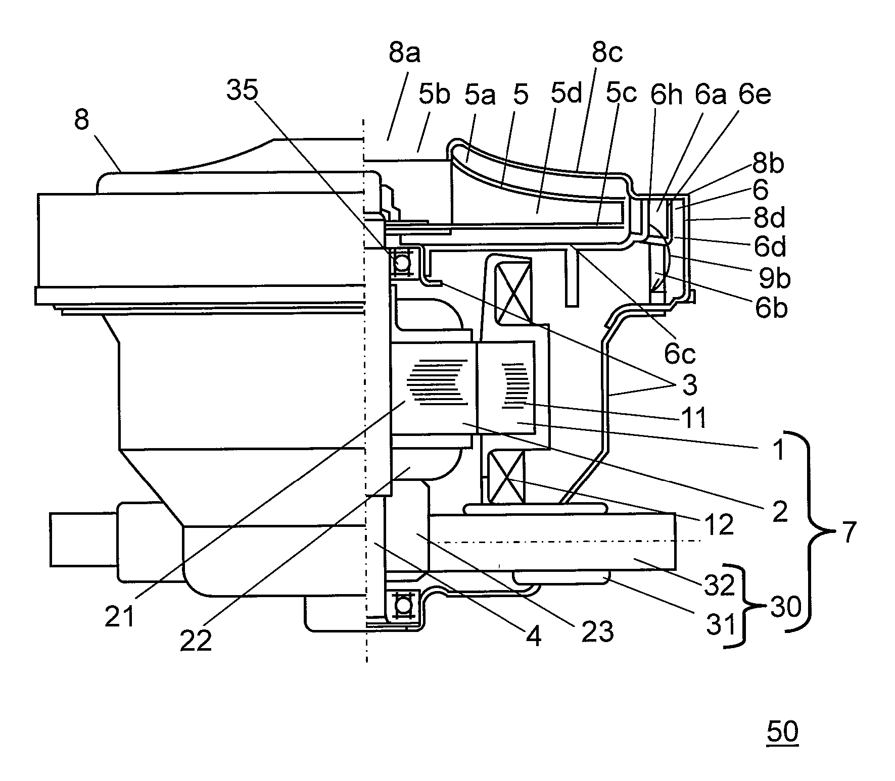
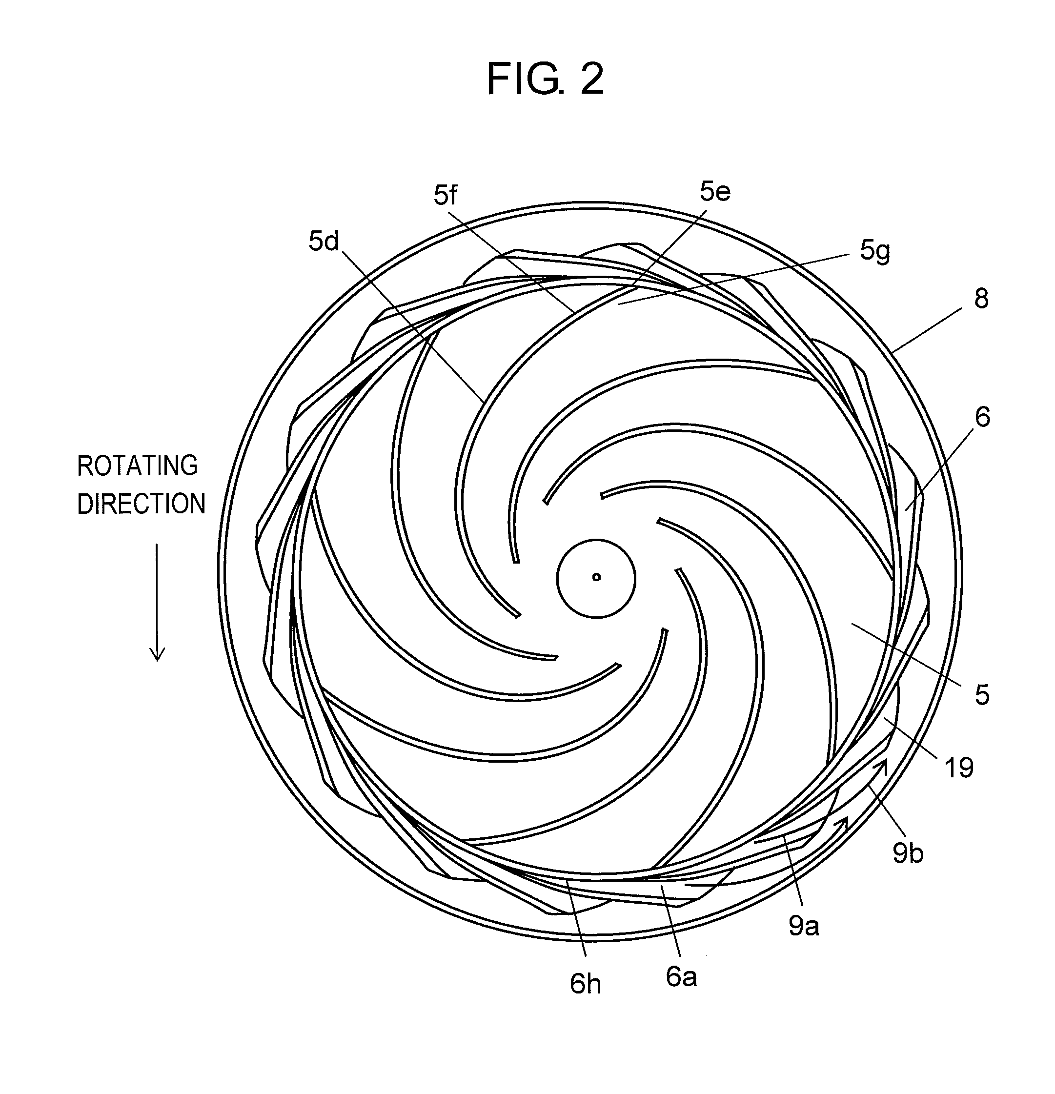
[0034]FIG. 1 is a sectional view of electric blower 50 according to the first embodiment of this invention.
[0035]Electric blower 50 comprises electric motor 7, bracket 3, rotary fan 5, air guide 6 and fan case 8. Electric motor 7 further comprises stator 1, rotor 2 and brush unit 30.
[0036]In electric motor 7, stator 1 is formed of field winding 12 wound around field core 11.
[0037]Rotor 2 comprises armature core 21, armature winding 22, commutator 23 and output shaft 4. Armature winding 22 is partially connected to commutator 23. Armature core 21 includes armature winding 22 wound around it. This commutator 23 and armature core 21 are coupled to output shaft 4. Rotor 2 of such a structure is disposed and supported inside stator 1 in a manner to be rotatable around output shaft 4.
[0038]Stator 1 is fixed inside bracket 3. Bracket 3 is also provided wit...
second exemplary embodiment
[0076]Description is provided hereinafter of the second embodiment by referring to the accompanying drawings. Like reference marks are used to designate like components as those of the first embodiment, and detailed explanation of them will be skipped. Fan case shoulder 8b of the second embodiment is formed into a circular arc shape, as compared with that of the first embodiment.
[0077]FIG. 6A is a sectional view of diffuser 6a according to the second embodiment. FIG. 6B is a sectional view of fan case 8 according to the second embodiment.
[0078]As shown in FIG. 6A, a portion of diffuser shoulder 6e of diffuser 6a shown by hatched lines is cut by means of cutting so that diffuser shoulder 6a is formed to have a circular arc shape in its meridian plane. In addition, fan case shoulder 8b of fan case 8 is formed to have a small circular arc shape in the meridian plane as shown in FIG. 6B. In other words, fan case shoulder 8b in this embodiment has a fillet formed in the circumferential d...
third exemplary embodiment
[0093]Any of electric blowers 50 discussed in the above embodiments can be mounted to a vacuum cleaner. Description is provided of an example of vacuum cleaner equipped with electric blower 50 in one of the first embodiment and the second embodiment.
[0094]FIG. 9 is an external view of the vacuum cleaner according to the third exemplary embodiment of this invention.
[0095]As shown in FIG. 9, main cleaner unit 41 is provided with wheel 42 and caster 43 mounted to its outer body. This is to allow main cleaner unit 41 to move freely on a floor surface.
[0096]Main cleaner unit 41 also has suction port 45 formed in a lower portion thereof, wherein suction hose 46 and extension pipe 48 provided with handle 47 are connected one after another. Floor nozzle 49 is attached to the end of extension pipe 48.
[0097]Main cleaner unit 41 has electric blower 50 of the above embodiment built in it, and electric blower 50 includes electric motor 7. Dust collection case 44 is disposed inside main cleaner u...
PUM
 Abstract
Description
Claims
Application Information