Sleeve and rod support for fuel bladder

a fuel bladder and support technology, applied in the field of aircraft, can solve the problems of not being able to use or present sponsons for fuel bladder installation, difficult and costly mounting of the bladder in such a chamber,

Active Publication Date: 2013-08-22
SIKORSKY AIRCRAFT CORP
View PDF0 Cites 12 Cited by
  • Summary
  • Abstract
  • Description
  • Claims
  • Application Information

AI Technical Summary

Problems solved by technology

Mounting the bladder in such a chamber is typically difficult and costly.
In some a...

Method used


Image

  • Sleeve and rod support for fuel bladder
  • Sleeve and rod support for fuel bladder
  • Sleeve and rod support for fuel bladder

Examples


Embodiment Construction

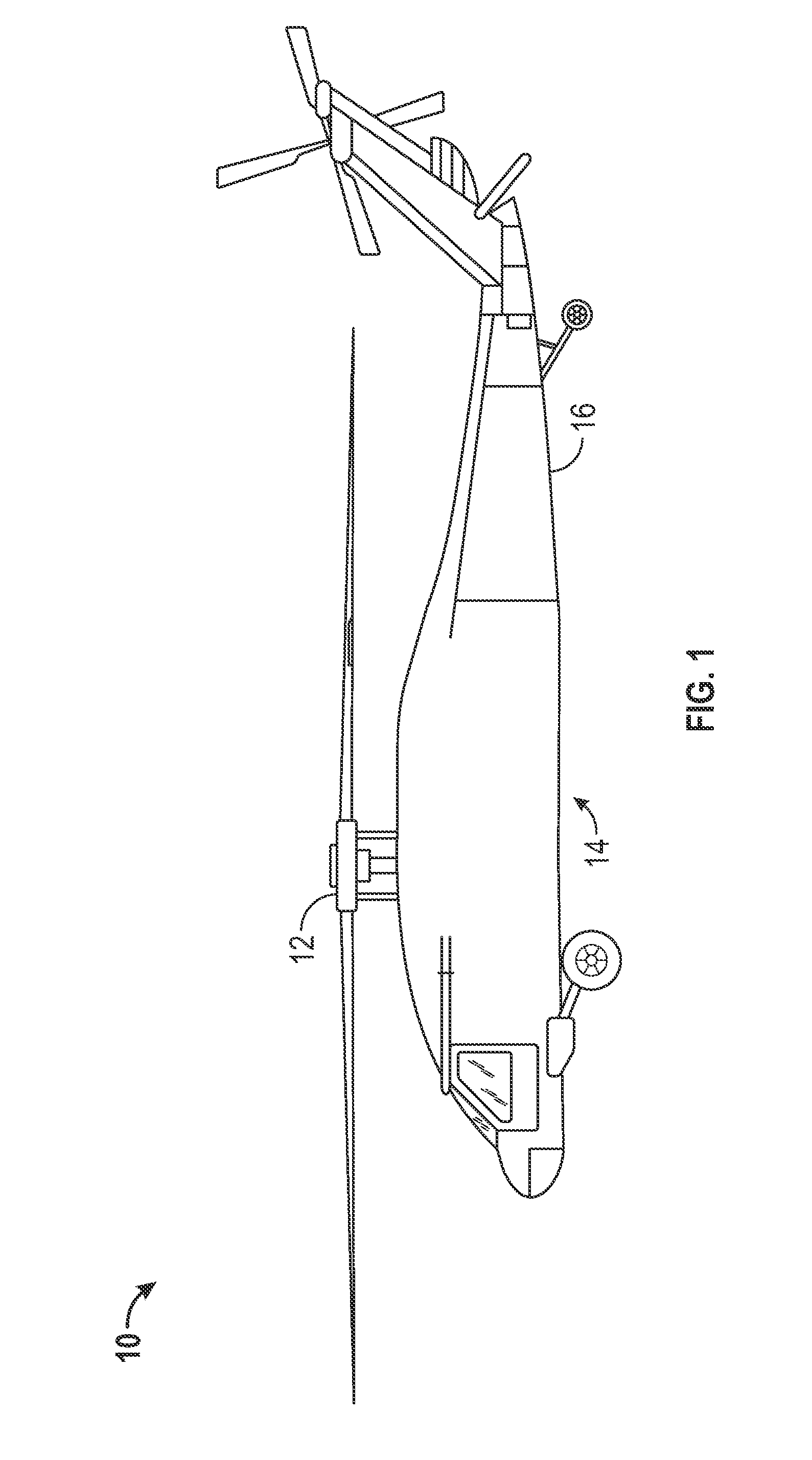
[0020]Shown in FIG. 1 is a schematic of a rotary wing aircraft, in this embodiment, a helicopter 10. The helicopter 10 includes a main rotor assembly 12, and a fuselage 14 having an extending tail 16.

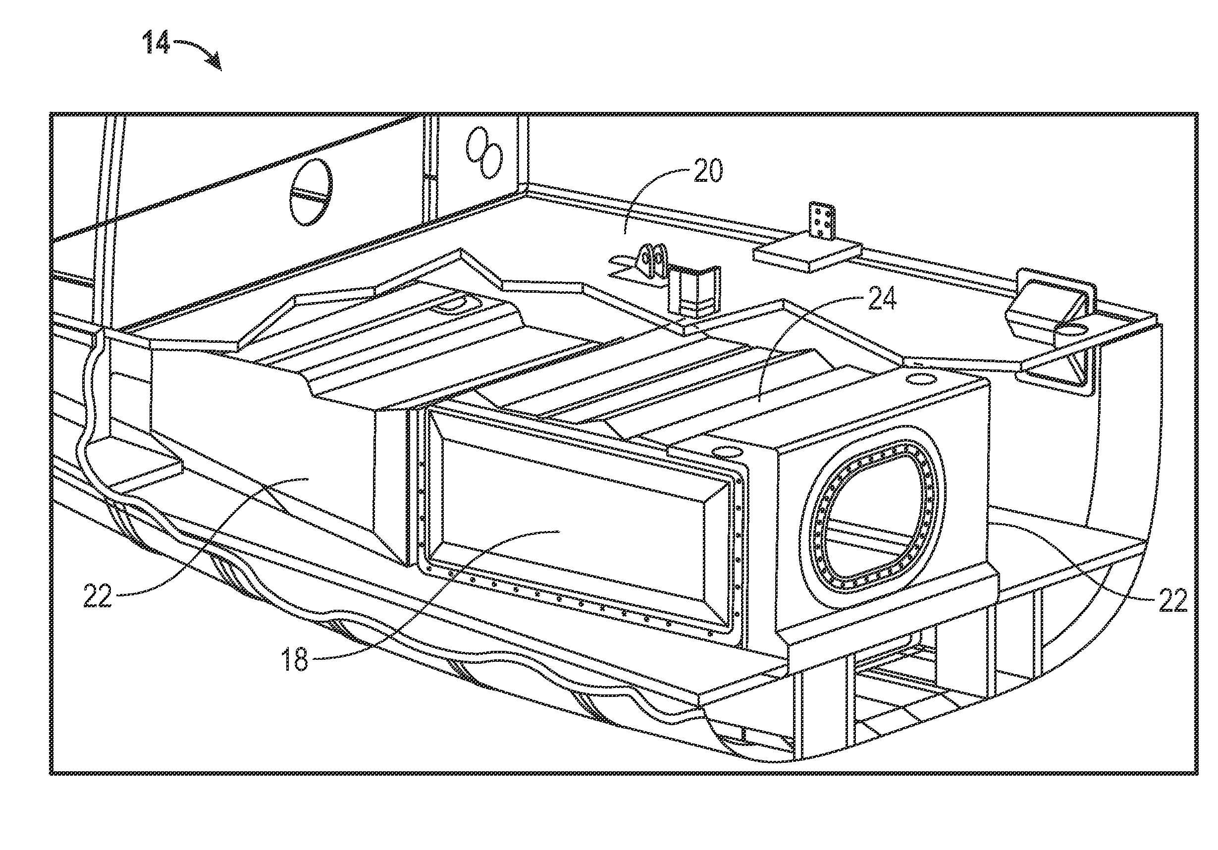
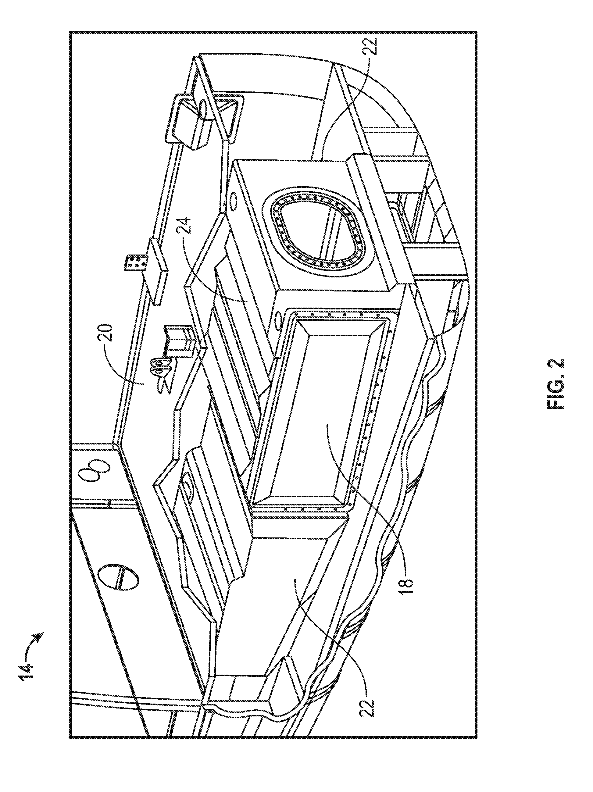
[0021]Referring to FIGS. 2 and 3, a flexible fuel bladder 18 is located in the fuselage 14. The bladder 18 is positioned in the fuselage 14 below a deck, for example, a transmission deck 20 and between two keels 22, which in some embodiments extend substantially perpendicular to the transmission deck 20. The bladder 18 includes a top portion 24 closest to the transmission deck 20.

[0022]Referring to FIG. 4, the bladder 18 includes a securing structure at the top portion 24 to secure the bladder 18 in the fuselage 14. The securing structure includes one or more sleeves 26, in some embodiments formed substantially integrally with the bladder 18, at a top portion 24 of the bladder 18. The sleeves 26 extend from a first side 28 of the bladder 18 to a second side 30 of the bladder 18 between ...


PUM

PropertyMeasurementUnit
Flexibilityaaaaaaaaaa

Abstract

A flexible fuel bladder structure for an aircraft includes one or more sleeves extending along an exterior of the fuel bladder. The one or more sleeves are receptive of one or more rods to at least partially suspend the fuel bladder in the aircraft. An aircraft includes a fuselage and a flexible fuel bladder disposed in the fuselage. One or more rods are installed through a portion of the fuel bladder and into a fuselage member. The flexible fuel bladder is at least partially suspended from the one or more rods. A method of installing a fuel bladder in an aircraft includes inserting a flexible bladder into a fuselage space of the aircraft. One or more rods are installed through one or more fuselage members and one or more sleeves of the fuel bladder. The one or more rods at least partially suspend the fuel bladder in the fuselage.

Description

BACKGROUND OF THE INVENTION[0001]The subject matter disclosed herein relates to aircraft. More specifically, the subject disclosure relates to fuel bladder structures for aircraft.[0002]Aircraft, such as airplanes, helicopters, turbo props and tilt rotor aircraft typically often include one or more flexible containers, or bladders, for storage of fuel on board the aircraft. The bladder provides a sealed volume for the storage of fuel as an alternative to forming a sealed chamber in the aircraft structure. Mounting the bladder in such a chamber is typically difficult and costly. The bladders include fittings and / or connections for filling the bladder with fuel, outputting the fuel to an aircraft engine, and may also include ancillary components such as fuel pumps and fuel filters and vent fittings.[0003]In a typical aircraft, most often a helicopter, the bladders are contained in sponsons, or projections from the fuselage of the aircraft. As such, the fuel bladders are contained in a...

Claims


Application Information

Patent Timeline
IPC IPC(8): B64D37/04B23P11/00B64D37/06
CPCB23P11/00Y10T29/49947B64D37/06B64D37/04
Inventor BOFILL, STEVEN
Owner SIKORSKY AIRCRAFT CORP
Why Eureka
Try Eureka