Valve assembly for inflatable bladder and method of manufacturing the same

a valve assembly and inflatable technology, applied in the field of valve assembly, can solve the problems of air valves having no protective structure to absorb force, plugs made of compressible materials may fail after use, and the inside diameter dimension of air valves known in the prior art is small, so as to achieve the effect of increasing strength and durability

Active Publication Date: 2019-09-10
NSI INT
View PDF44 Cites 0 Cited by
  • Summary
  • Abstract
  • Description
  • Claims
  • Application Information

AI Technical Summary

Benefits of technology

[0018]The primary objective of the present invention is to provide an improved air valve assembly for inflatable bodies typically made from thermoplastic rubber material and the like which will exhibit significantly increased strength and durability during inflation and while inflated, especially at and around the interface between the air valve assembly and the bounding wall of the inflatable body.
[0019]In accordance with one aspect of the invention, there is provided an air valve assembly for attachment to an inflatable thermoplastic rubber bladder or bounding wall structure, the air valve assembly comprising a valve member having a flange extending radially therefrom, the valve member including a bore formed therein and a slot valve extending therefrom with a central opening communicating with the bore of the valve member. The opening of the slot valve has an inner diameter such that air may not flow in a reverse direction therethrough. The valve member further comprises an integrally bonded o-ring around the bore of the valve member, the o-ring providing added strength and durability during and after inflation of the inflatable bladder or bounding wall. The valve member including a peripheral sealing flange extended radially therefrom for attaching to the bladder or bounding wall. At least one of said body member, said inflatable body, and both said body member and said inflatable body is made from a material selected from the group consisting of thermoplastic elastomer (TPE), thermoplastic rubber (TPR), polyester-based polyurethane, polyether-based polyurethane, polyvinyls, polyesters, polyethers, rubber, latex, nylon, vinyl, polvchloroprene, synthetic fabric, synthetic rubber, natural rubber, Mediprene®, Dryflex®, Dynalloy® and Versaflex®. An air valve assembly may include: a valve member for attaching to said inflatable body, said valve member including a cylindrical body having a bore formed therein for receiving an air inflating valve coupling and for supplying air into said inflatable body, and a slot valve extending therefrom in fluid communicating with said bore; an o-ring integrally bonded within said cylindrical body of said valve member such that said o-ring encircles a portion of said bore; said o-ring member having an elastomeric coefficient less than an elastomeric coefficient of said inflatable body; and a peripheral sealing flange extended radially therefrom for attaching to said inflatable body. The valve member may be made of a material selected from the group consisting of thermoplastic elastomer (TPE), thermoplastic rubber (TPR), polyester-based polyurethane, polyether-based polyurethane, polyvinyls, polyesters, polyethers, rubber, latex, nylon, vinyl, polychloroprene, synthetic fabric, synthetic rubber, natural rubber, Mediprene®, Dryflex®, Dynalloy® and Versaflex®. The o-ring may be made of a material selected from the group consisting of thermoplastic elastomer (TPE), thermoplastic rubber (TPR), polyester-based polyurethane, polyether-based polyurethane, polyvinyls, polyesters, polyethers, rubber, latex, nylon, vinyl, polychloroprene, synthetic fabric, synthetic rubber, and natural rubber. The o-ring may be substantially formed from the same material as said valve member, said material of said o-ring being of a higher density than said material of said valve member. The o-ring may provide a snap-in fit for a pump valve coupling during filling of said inflatable body.

Problems solved by technology

Unfortunately, the inside diameter dimension of the air valves known in the prior art is small.
However, the plug which is made of compressible material may fail after use.
In addition, the air valve has no protective structure to absorb a force from the inflating needle.
However, the protective bonnet is spaced away from the needle passageway of the plug, and may not be used to block the needle passageway of the plug when the plug has become failure after use.
On the other hand, TPEs / TPRs, relative to conventional rubber or thermoset, require relatively more expensive raw materials, are generally unable to be loaded with low cost fillers, such as carbon black (therefore preventing TPEs from being used in automobile tires), have poor chemical and heat resistance, and have high compression set and low thermal stability.
Also, TPEs / TPRs may soften or melt at elevated temperatures above which they lose their rubbery behaviour.

Method used


Image

  • Valve assembly for inflatable bladder and method of manufacturing the same
  • Valve assembly for inflatable bladder and method of manufacturing the same
  • Valve assembly for inflatable bladder and method of manufacturing the same

Examples


Embodiment Construction

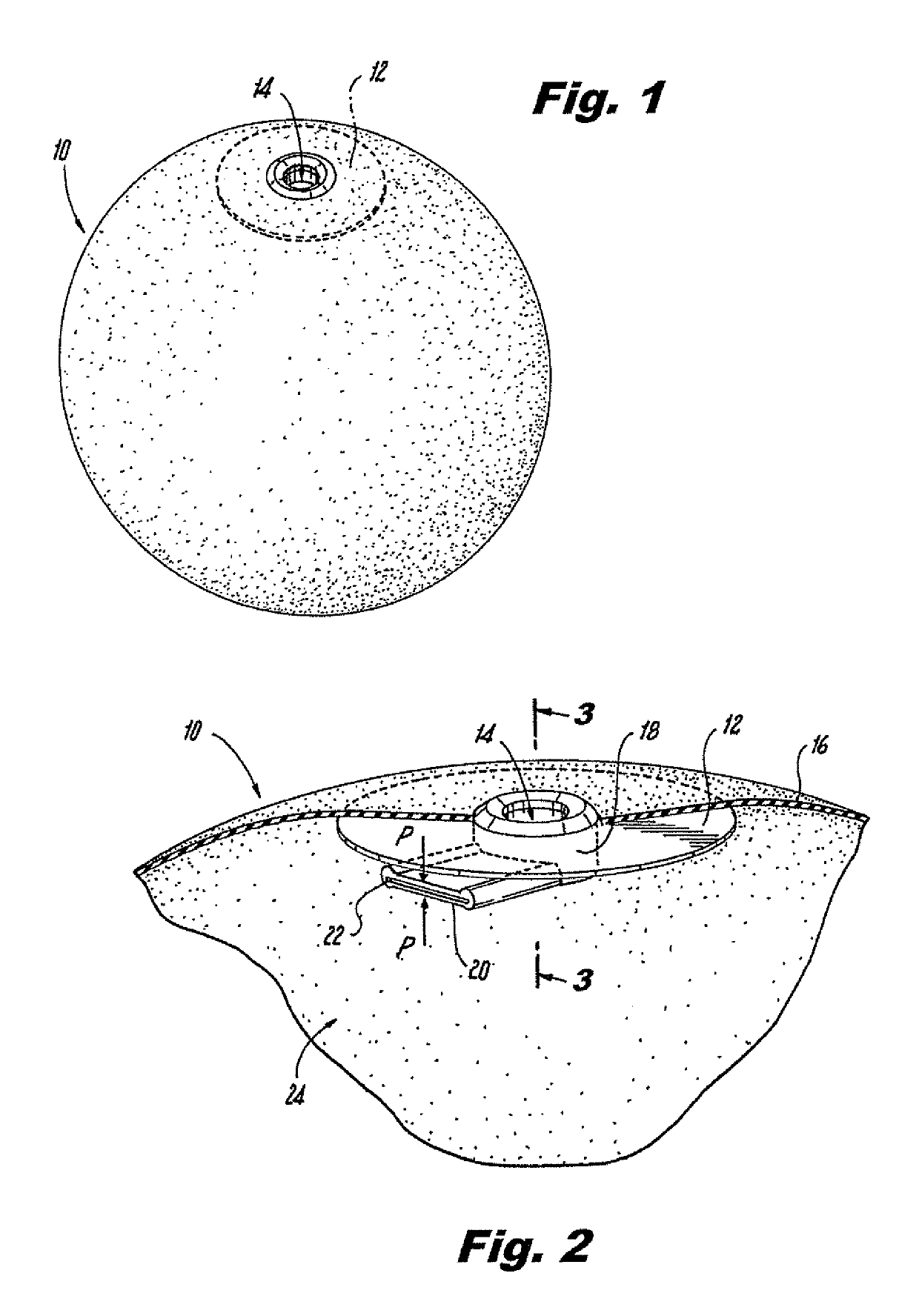
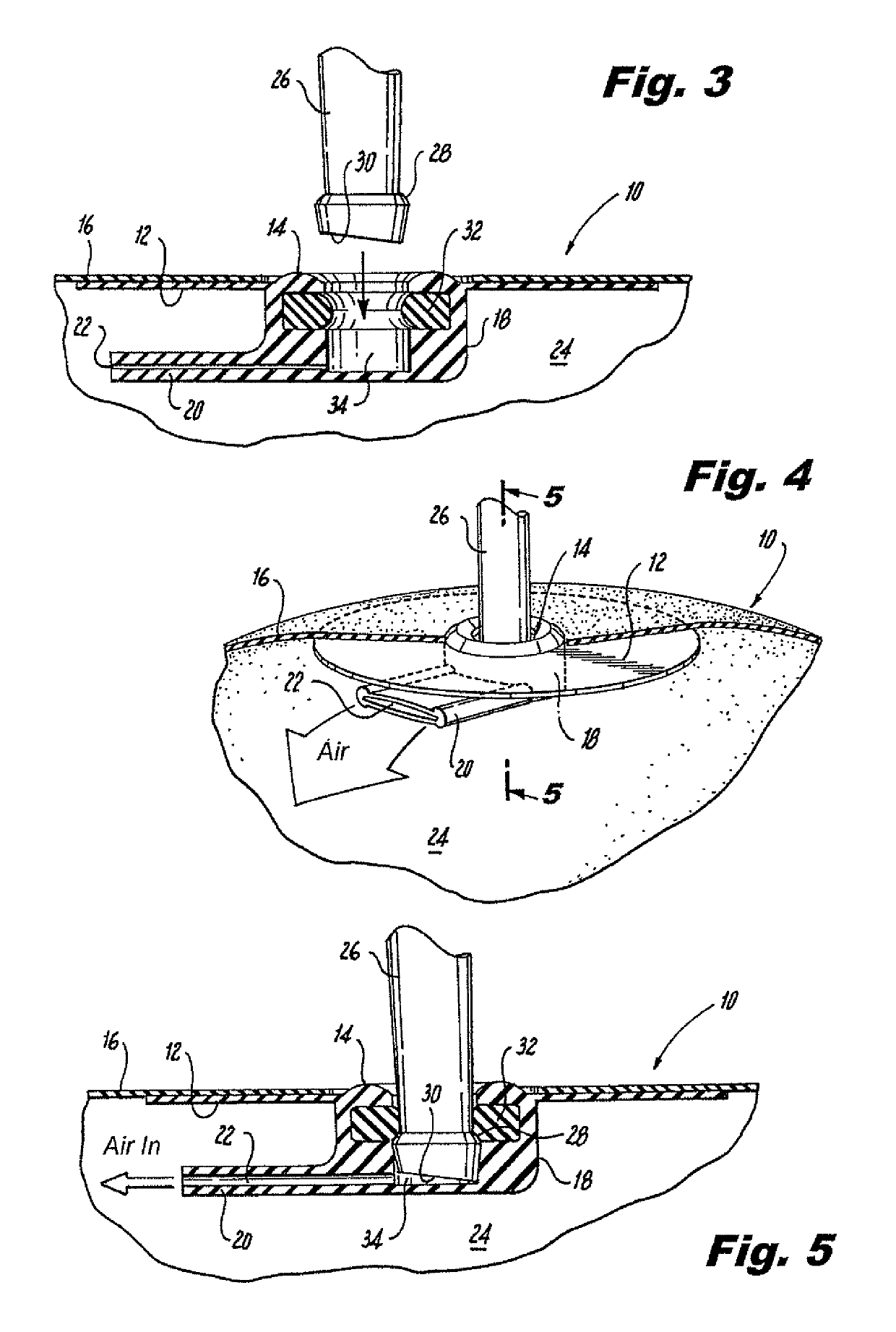
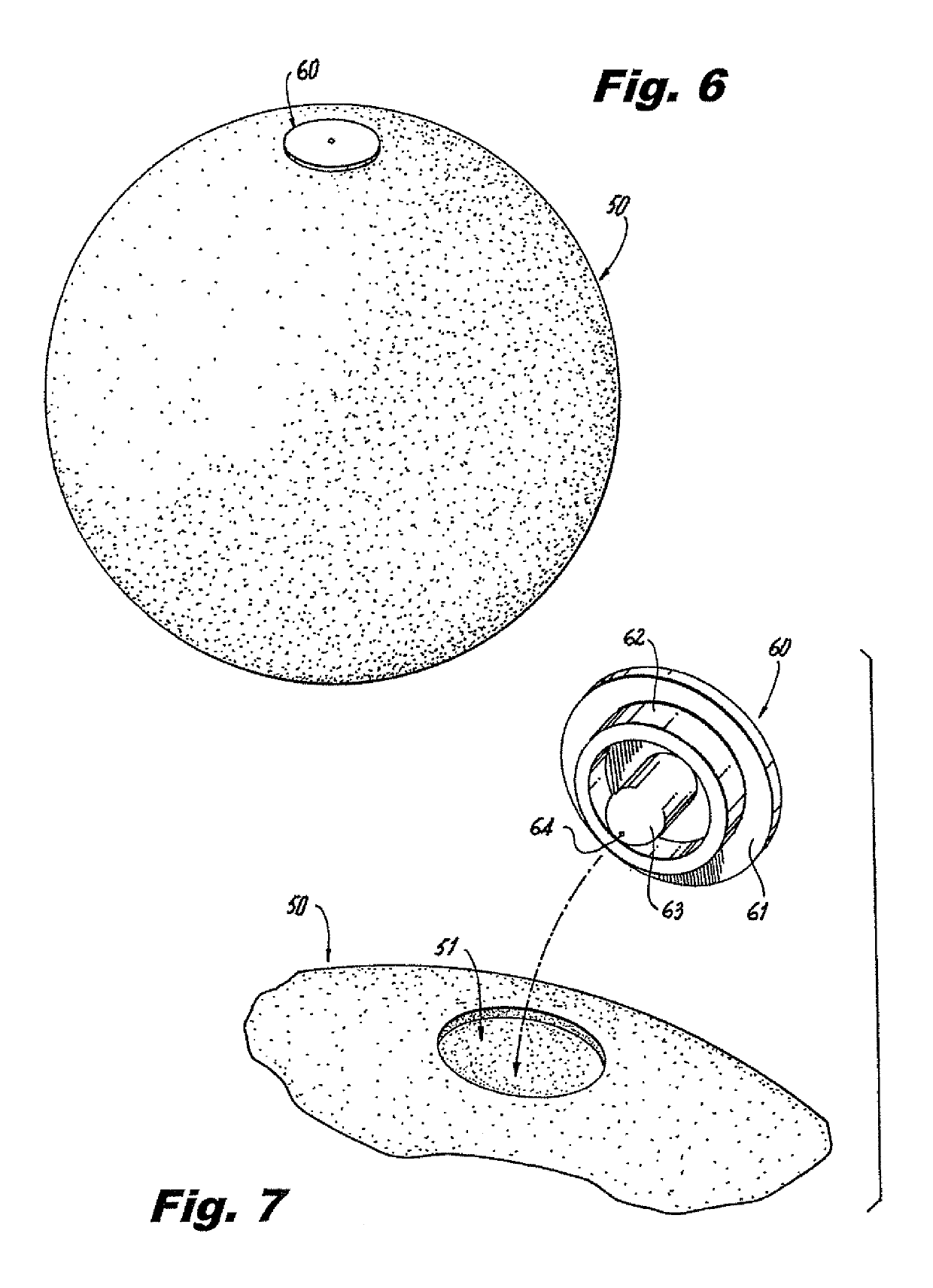
[0040]As required, a detailed illustrative embodiment of the present invention is disclosed herein. However, techniques, systems, compositions and operating structures in accordance with the present invention may be embodied in a wide variety of sizes, shapes, forms and modes, some of which may be quite different from those in the disclosed embodiment. Consequently, the specific structural and functional details disclosed herein are merely representative, yet in that regard, they are deemed to afford the best embodiment for purposes of disclosure and to provide a basis for the claims herein which define the scope of the present invention.

[0041]Reference will now be made in detail to several embodiments of the invention that are illustrated in the accompanying drawings. Wherever possible, same or similar reference numerals are used in the drawings and the description to refer to the same or like parts or steps. The drawings are in simplified form and are not to precise scale. For pur...


PUM

PropertyMeasurementUnit
lengthaaaaaaaaaa
radiusaaaaaaaaaa
radiusaaaaaaaaaa

Abstract

The present invention relates to inflatable bodies or systems with bounding walls or bladder structures and at least one valve assembly thermally bonded thereto. More particularly, the present invention provides a valve assembly for inflatable bodies typically made from a thermoplastic rubber material or the like, which will exhibit significantly increased strength and durability during inflation and while inflated, especially at and around the interface between the air valve assembly and the bounding wall of the inflatable body because of the enhanced strength of the interface through thermal sealing.

Description

CROSS REFERENCE TO RELATED APPLICATIONS[0001]This application relates to and claims priority from International Application No. PCT / US2014 / 017819 filed Feb. 21, 2014, the entire contents of which are incorporated by reference, which in turn claims priority to U.S. Provisional Ser. No. 61 / 768,280 filed Feb. 22, 20013.BACKGROUND OF THE INVENTIONField of the Invention[0002]The present invention relates to inflatable bodies or systems with bounding walls or bladder structures and at least one valve assembly. More particularly, the present invention provides a valve assembly for inflatable bodies typically made from thermoplastic rubber material and the like which will exhibit significantly increased strength and durability during inflation and while inflated especially at and around the interface between the air valve assembly and the bounding wall of the inflatable body.Description of the Related Art[0003]The prior art is directed to methods and apparatus for flexible air valves for us...

Claims


Application Information

Patent Timeline
Patent Type & Authority Patents(United States)
IPC IPC(8): F16K15/20B29C49/42
CPCF16K15/202F16K15/20B29C49/4252Y10T137/3584A63B41/04Y10T137/0486
Inventor LANDI, JR., FRANK J.
Owner NSI INT
Why Eureka
Try Eureka