Illuminating device and display device provided with same

a technology of illumination device and display device, which is applied in the direction of lighting and heating apparatus, instruments, mechanical equipment, etc., can solve the problems of uneven brightness of images displayed, reduce the manufacturing cost of display device that uses diffusion sheet, and reduce uneven brightness

Active Publication Date: 2014-01-16
SHARP KK
View PDF7 Cites 8 Cited by
  • Summary
  • Abstract
  • Description
  • Claims
  • Application Information

AI Technical Summary

Benefits of technology

[0024]According to the first aspect of the present invention, unevenness in the brightness of the light emitted from the illumination device is reduced, so the images displayed on the screen are uniform regardless of distance from the light-emitting diodes. It is also not necessary to provide cut-out parts on the diffusion sheet, so the manufacturing cost of a display device that uses such a diffusion sheet is also reduced.
[0025]The second aspect of the present invention has similar effects to the first aspect of the present invention.
[0026]The third aspect of the present invention has similar effects to the first aspect of the present invention.
[0027]The fourth aspect of the present invention has similar effects to the first aspect of the present invention. Light emitted from the light guide plate passes through the diffusion sheet right before being radiated on the rear of the display panel, and thus the light is radiated on the display panel in a sufficiently diffused state. This further reduces unevenness in the brightness.
[0028]According to the fifth aspect of the present invention, it is not necessary to provide cut-out parts on the diffusion sheet, so the frame of the display panel can be made narrower.

Problems solved by technology

As such, the attachment position of the LEDs leads to differences in brightness of the backlight radiated from the backlight device, resulting in unevenness in the brightness of the images displayed.

Method used


Image

  • Illuminating device and display device provided with same
  • Illuminating device and display device provided with same
  • Illuminating device and display device provided with same

Examples


embodiment 1

[0063]

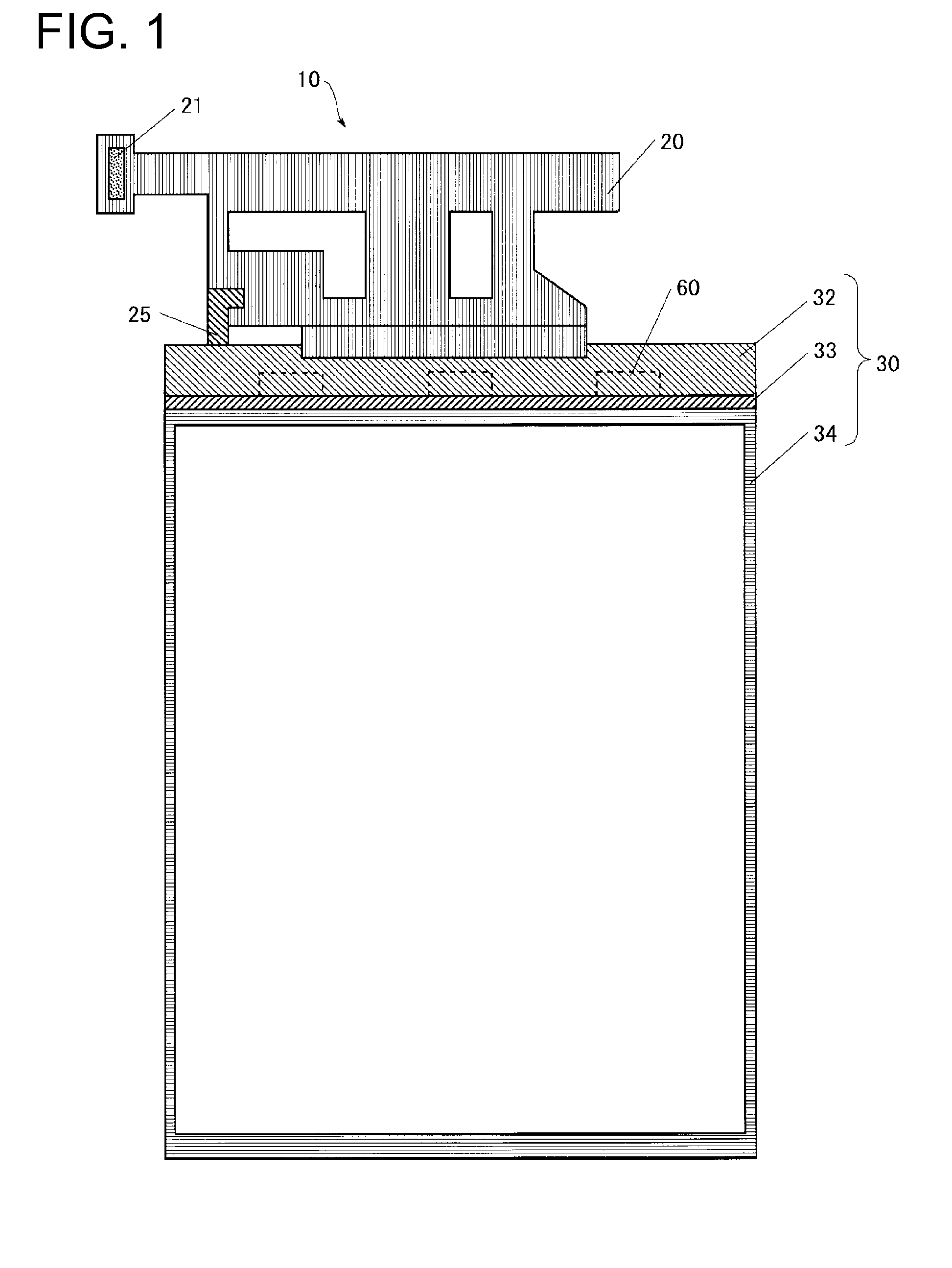
[0064]A configuration of a liquid crystal module included in a liquid crystal display device 200 of Embodiment 1 is the same as the configuration of the liquid crystal module 10 in FIG. 1, so the drawings and explanations showing a configuration of the liquid crystal module will be omitted.

[0065]

[0066]FIG. 7 is a cross-sectional view showing main parts of the liquid crystal display device 200 of Embodiment 1, and FIG. 8 is a plan view showing a configuration of the liquid crystal display device 200 shown in FIG. 7. The components shown in FIGS. 7 and 8 that are the same as those shown in FIGS. 2 and 3 are given the same reference characters and the explanation thereof will be omitted. Only the components that are different will be explained.

[0067]As shown in FIGS. 7 and 8, a backlight device 240 of the liquid crystal display device 200 differs from the backlight device 40 of the liquid crystal display device 100 in that an end portion of a diffusion sheet 270 is in a location ...

embodiment 2

[0073]

[0074]A configuration of a liquid crystal module included in a liquid crystal display device 300 of Embodiment 2 is the same as the configuration of the liquid crystal module 10 in FIG. 1, so the drawings and explanations showing a configuration of the liquid crystal module will be omitted.

[0075]

[0076]FIG. 11 is a cross-sectional view of main parts of the liquid crystal display device 300 according to Embodiment 2. The components shown in FIG. 11 that are the same as those shown in FIG. 2 are given the same reference characters and the explanation thereof will be omitted. Only the components that are different will be explained. The plan view showing a configuration of the liquid crystal display device 300 shown in FIG. 11 is the same as the plan view shown in FIG. 8, and thus will be omitted.

[0077]As shown in FIG. 11, a backlight device 340 of the liquid crystal display device 300 differs from the backlight device 340 of the liquid crystal display device 100 in that an end po...

embodiment 3

[0083]

[0084]A configuration of a liquid crystal module included in a liquid crystal display device 400 of Embodiment 3 is the same as the configuration of the liquid crystal module 10 in FIG. 1, so the drawings and explanations showing the liquid crystal module will be omitted.

[0085]

[0086]FIG. 13 is a cross-sectional view showing main parts of the liquid crystal display device 400 of Embodiment 3, and FIG. 14 is a plan view showing a configuration of the liquid crystal display device 400 shown in FIG. 13. The components shown in FIGS. 13 and 14 that are the same as those shown in FIGS. 2 and 3 are given the same reference characters and the explanation thereof will be omitted. Only the components that are different will be explained.

[0087]A backlight device 440 of the liquid crystal display device 400 differs from the liquid crystal display device 100 shown in FIG. 2 in that an optical sheet 75 is attached to the surface of a light guide plate 50, and a diffusion sheet 470 is attach...


PUM


Abstract

The present invention allows light leaked to outside of a light guide plate (50) from a surface area L to pass through a diffusion sheet (70) by covering both the bottom of an optical sheet (75) and the surface area L of the light guide plate (50) located between an LED FPC (25) and the optical sheet (75) with the diffusion sheet (70). This irradiates a liquid crystal display panel (30) with light after the light leaked to outside from the surface area L is diffused by the diffusion sheet (70), so unevenness in the brightness of backlight emitted from a backlight device (240) can be reduced. Thus, the brightness of images displayed on a screen can be made uniform regardless of distance to an LED (60).

Description

TECHNICAL FIELD[0001]The present invention relates to an illumination device and a display device provided therewith, and in particular relates to an illumination device using a light-emitting diode as a light source and a display device provided therewith.BACKGROUND ART[0002]Light-emitting diodes (LEDs) with low power consumption have recently been replacing conventional cold cathode fluorescent lamps (CCFLs) as light sources for the backlight device (also called “illumination device”) included in liquid crystal display devices. In backlight devices that use LEDs as the light source, a plurality of LEDs are arranged in a row with spaces therebetween on an end of a light guide plate. In liquid crystal display devices that include such a backlight device, images displayed on areas close to the LEDs become brighter, and images displayed on areas far from the LEDs become darker. As such, the attachment position of the LEDs leads to differences in brightness of the backlight radiated fr...

Claims


Application Information

Patent Timeline
Patent Type & Authority Applications(United States)
IPC IPC(8): F21V8/00
CPCG02B6/0051G02B6/0028G02B6/0068G02B6/0073G02F1/133615G02F1/133325
Inventor MINOURA, KAZUNORI
Owner SHARP KK
Why Eureka
Try Eureka