Eureka AIR delivers breakthrough ideas for toughest innovation challenges, trusted by R&D personnel around the world.

Display device and method of manufacturing the same

a technology of display device and manufacturing method, which is applied in the direction of optics, instruments, non-linear optics, etc., can solve the problems of high complex manufacturing process, and increased cost of reflective layer manufacturing, and achieve low cost and improved reflectance

Active Publication Date: 2018-08-09
SAMSUNG DISPLAY CO LTD
View PDF9 Cites 11 Cited by
  • Summary
  • Abstract
  • Description
  • Claims
  • Application Information

AI Technical Summary

Benefits of technology

The invention is about a display device that includes a reflective layer and can be made at a low cost and with improved reflectance. The methods of manufacturing the device use a reflective layer that can be formed using an inkjet process, instead of a more expensive chemical vapor deposition process. This reduces the manufacturing cost of the display device and makes it more affordable. Overall, the invention provides a way to create a reflective display device at a low cost and with improved performance.

Problems solved by technology

This type of LCD device needs a reflective layer for reflecting light of the particular wavelength band emitted from the fluorescent substance or the phosphor toward the front of the LCD device, i.e., in a direction toward the observer, but the manufacturing process is complex typically requiring multiple steps and cost to manufacture the reflective layer is generally high.
For example, cholesteric liquid crystal layers can be formed in exemplary methods by an inkjet process, rather than by a Chemical Vapor Deposition (CVD) process, which is more costly.

Method used


Image

  • Display device and method of manufacturing the same
  • Display device and method of manufacturing the same
  • Display device and method of manufacturing the same

Examples


Embodiment Construction

[0045]In the following description, for the purposes of explanation, numerous specific details are set forth in order to provide a thorough understanding of various exemplary embodiments. It is apparent, however, that various exemplary embodiments may be practiced without these specific details or with one or more equivalent arrangements. In other instances, well-known structures and devices are shown in block diagram form in order to avoid unnecessarily obscuring various exemplary embodiments.

[0046]In the accompanying figures, the size and relative sizes of layers, films, panels, regions, etc., may be exaggerated for clarity and descriptive purposes. Also, like reference numerals denote like elements.

[0047]When an element or layer is referred to as being “on,”“connected to,” or “coupled to” another element or layer, it may be directly on, connected to, or coupled to the other element or layer or intervening elements or layers may be present. When, however, an element or layer is re...


PUM

PropertyMeasurementUnit
central wavelengthaaaaaaaaaa

Abstract

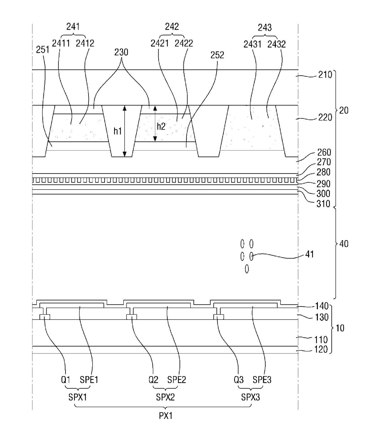
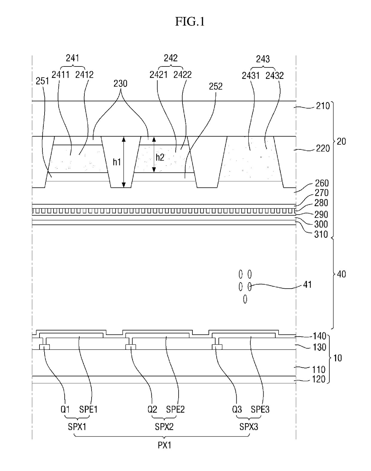
A display device including a first substrate, a pixel unit disposed on the first substrate and including a first sub-pixel electrode, a second sub-pixel electrode and a third sub-pixel electrode, the first through third sub-pixel electrodes being adjacent to one another, a second substrate facing the first substrate, a first wavelength conversion layer disposed on a surface of the second substrate facing the first substrate, and overlapping the first sub-pixel electrode, a second wavelength conversion layer disposed on the surface of the second substrate facing the first substrate, and overlapping the second sub-pixel electrode, a transmissive layer disposed on the surface of the second substrate facing the first substrate, and overlapping the third sub-pixel electrode, a first cholesteric liquid crystal layer disposed on a surface of the first wavelength conversion layer facing the first substrate, a second cholesteric liquid crystal layer disposed on a surface of the second wavelength conversion layer facing the first substrate, and a planarization layer disposed on the surfaces of the first and second cholesteric liquid crystal layers facing the first substrate and on a surface of the transmissive layer facing the first substrate. Methods of manufacturing a display device capable of reducing the number of process steps in the manufacturing process are also disclosed.

Description

CROSS-REFERENCE TO RELATED APPLICATION[0001]This application claims priority from and the benefit of Korean Patent Application No. 10-2017-0017342, filed on Feb. 8, 2017, which is hereby incorporated by reference for all purposes as if fully set forth herein.BACKGROUNDField[0002]The invention relates generally to a display device and a method of manufacturing the same, and, more particularly, to a display device having a reflective layer, and a method of manufacturing the same.Discussion of the Background[0003]The importance of display devices has steadily grown with recent developments in multimedia technology. As a result, a variety of display devices such as a liquid crystal display (LCD) device, an organic light-emitting diode (OLED) display device, and the like have been developed and are now widespread.[0004]The LCD device, which is one of the most widely-used flat panel displays, includes two substrates on which field-generating electrodes such as pixel electrodes and a commo...

Claims


Application Information

Patent Timeline
Patent Type & Authority Applications(United States)
IPC IPC(8): G02F1/1335G02F1/1337
CPCG02F1/133617G02F1/133723G02F1/133514G02F1/133621G02F1/133512G02F1/133528G02F1/133555G02F1/13624G02F1/1368G02F2001/133614G02F2203/055G02F2202/36G02F2001/133357G02F2001/133548G02F2201/123G02F1/134309G02F1/13718G02F1/133553G02F1/133516G02F1/133357G02F1/133548G02F1/133614
Inventor SHIN, KI CHULOH, HO KIL
Owner SAMSUNG DISPLAY CO LTD
Why Eureka
Eureka Blog
Learn More