Optical fiber for chemical sensor

a technology of optical fiber and chemical sensor, which is applied in the direction of cladded optical fibre, instruments, optical elements, etc., can solve the problems of difficult manufacturing of optical fiber and relatively narrow width of optical transmission band, and achieve high measurement sensitivity

Inactive Publication Date: 2014-02-06
GWANGJU INST OF SCI & TECH
View PDF12 Cites 17 Cited by
  • Summary
  • Abstract
  • Description
  • Claims
  • Application Information

AI Technical Summary

Benefits of technology

[0011]It is an aspect of the present invention to provide an optical fiber that increases an evanescent field fraction of an existing suspended core fiber to exhibit high measurement sensitivity, and a chemical sensor using the same.

Problems solved by technology

However, transmission of optical fibers is sensitively influenced by the characteristics of the band gap and the geometrical structure of the hole, and it is very difficult to manufacture the optical fiber and the width of the optical transmission band is relatively very narrow.

Method used


Image

  • Optical fiber for chemical sensor
  • Optical fiber for chemical sensor
  • Optical fiber for chemical sensor

Examples


Embodiment Construction

[0032]Exemplary embodiments of the present invention will now be described in detail with reference to the accompanying drawings. It should be understood that the present invention is not limited to the following embodiments and may be embodied in different ways, and that the embodiments are given to provide complete disclosure of the invention and to provide thorough understanding of the invention to those skilled in the art. The scope of the invention is limited only by the accompanying claims and equivalents thereof. Like components will be denoted by like reference numerals throughout the specification.

[0033]FIG. 5 is a sectional view of an optical fiber according to one embodiment of the present invention.

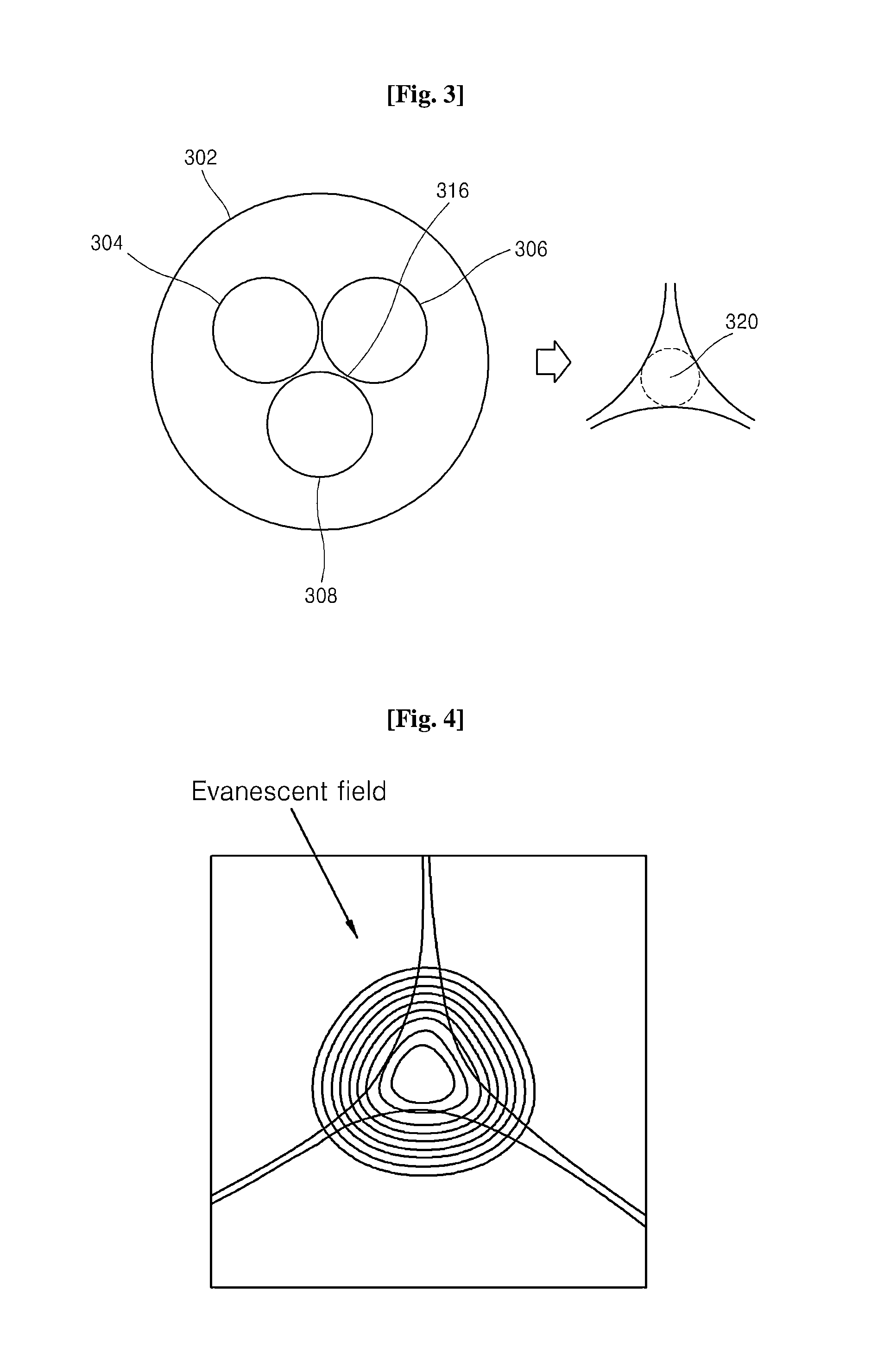
[0034]Referring to FIG. 5, an optical fiber 502 according to one embodiment of the invention includes a core area 512 and a cladding area. The cladding area surrounds the core area 512, and includes a monolayer with cladding holes 504, 506, 508 and an outskirt cladding region ...


PUM


Abstract

An optical fiber for an optical fiber sensor and a chemical sensor using the same are disclosed. The optical fiber includes a core area, and a suspended cladding area formed around the core area and having at least one cladding hole. The core area has at least one core hole for reducing an effective refractive index of the core area. The optical fiber and the chemical sensor using the same may have improved measurement sensitivity by increasing an evanescent field fraction of existing suspended core fibers.

Description

CROSS-REFERENCE TO RELATED APPLICATION[0001]This application claims priority to Korean Patent Application No. 10-2012-0084566 filed on 1 Aug. 2012, and all the benefits accruing therefrom under 35 U.S.C. §119, the contents of which is incorporated by reference in its entirety.BACKGROUND[0002]1. Technical Field[0003]The present invention relates to an optical fiber for an optical fiber sensor and a chemical sensor using the same.[0004]2. Description of the Related Art[0005]In recent years, numerous studies into chemical sensors using optical fibers have been conducted due to driving stability, optical connectivity, convenience, and high sensitivity thereof. In particular, optical fiber-based chemical sensor technology using multiple-hole optical fibers having holes in a core area or a cladding area have recently attracted much attention. Various properties such as optical absorption, refractive index, concentration, and density of gas, liquid, or solid filled inside the hole of the o...

Claims


Application Information

Patent Timeline
Patent Type & Authority Applications(United States)
IPC IPC(8): G02B6/02
CPCG02B6/02G01N21/3504G01N21/552G02B6/02323G02B6/02347G02B6/02385G02B6/028
Inventor KIM, BOK HYEONCHUNG, YOUNGJOOKIM, SO EUNKIM, BONGKYUNEOM, TAE JOONGOH, MYOUNG KYU
Owner GWANGJU INST OF SCI & TECH
Why Eureka
Try Eureka