Method of wind turbine yaw angle control and wind turbine

a technology of wind turbine and angle control, which is applied in the direction of wind turbines, wind energy generation, electrical equipment, etc., can solve the problems of inability to achieve ambiguous wind direction, inability to accurately yaw a usual wind turbine (wt), and inability to accurately measure the wind direction by means of anemometer wind vanes located on the nacelle of the wind turbine (wt) behind the turbulent air flow generated by the rotor,

Inactive Publication Date: 2014-06-19
MITA TEKNIK
View PDF5 Cites 28 Cited by
  • Summary
  • Abstract
  • Description
  • Claims
  • Application Information

AI Technical Summary

Benefits of technology

[0027]A time difference signal is low pass filtered to remove the high frequency components before being sent to a yaw actuator control module. The filtered time difference signal is sent to the input of the yaw actuator control module designed as P controller, PI controller, PID controller, neural-network controller, fuzzy logic controller, adaptive Kalman filter or look-up table for matching with the dynamic parameters of the structural components of a wind turbine and its environment, and where the control signal is generated for the yaw actuator.
[0028]The problem is also solved by the wind turbine for implementing the method according to the present invention, the said wind turbine comprising a nacelle mounted on the stationary tower and rotatable around the vertical axis, the rotor shaft placed in the nacelle and rotatable around the horizontal axis, the rotor of the wind turbine formed by at least two blades mounted on the shaft and transforming the kinetic energy of the wind into the rotational movement of the rotor shaft, the electric generator mechanically connected to the rotor shaft, the yaw controller the output of which is connected to the yaw actuator.
[0029]According to the present invention, the wind turbine contains a connected to the rotor shaft refer...

Problems solved by technology

The imperfection of the usual electromechanical and optical sensors (anemometer wind vanes), their location on the nacelle behind the turbine rotor, the necessity to calibrate them during wind turbine (WT) commissioning practically almost always cause inaccurate yawing of a usual wind turbine (WT).
The accuracy of measuring wind direction by means of anemometer wind vanes located on a wind turbine (WT) nacelle behind the turbulent air flow, generated by the rotor, is non-satisfying in most cases.
US 2009/0039651 A1 > published on Apr. 4, 2010 notes that it is very difficult to achieve an ambiguity of wind direction ranging within ±5° for an electromechanical anemometer wind vanes located on the aft of a nacelle considering all sources of measurement ambiguity.
Thus, an optimization of an error will lead to an increase in the wind turbine output power by 1.9%.
A yaw angle error has a greater scattering and output power is more sensitive to a yaw angle error when the wind velocities are low and moderate.
The sharp changes of a wind direction typical for these conditions cause varia...

Method used


Image

  • Method of wind turbine yaw angle control and wind turbine
  • Method of wind turbine yaw angle control and wind turbine
  • Method of wind turbine yaw angle control and wind turbine

Examples


Embodiment Construction

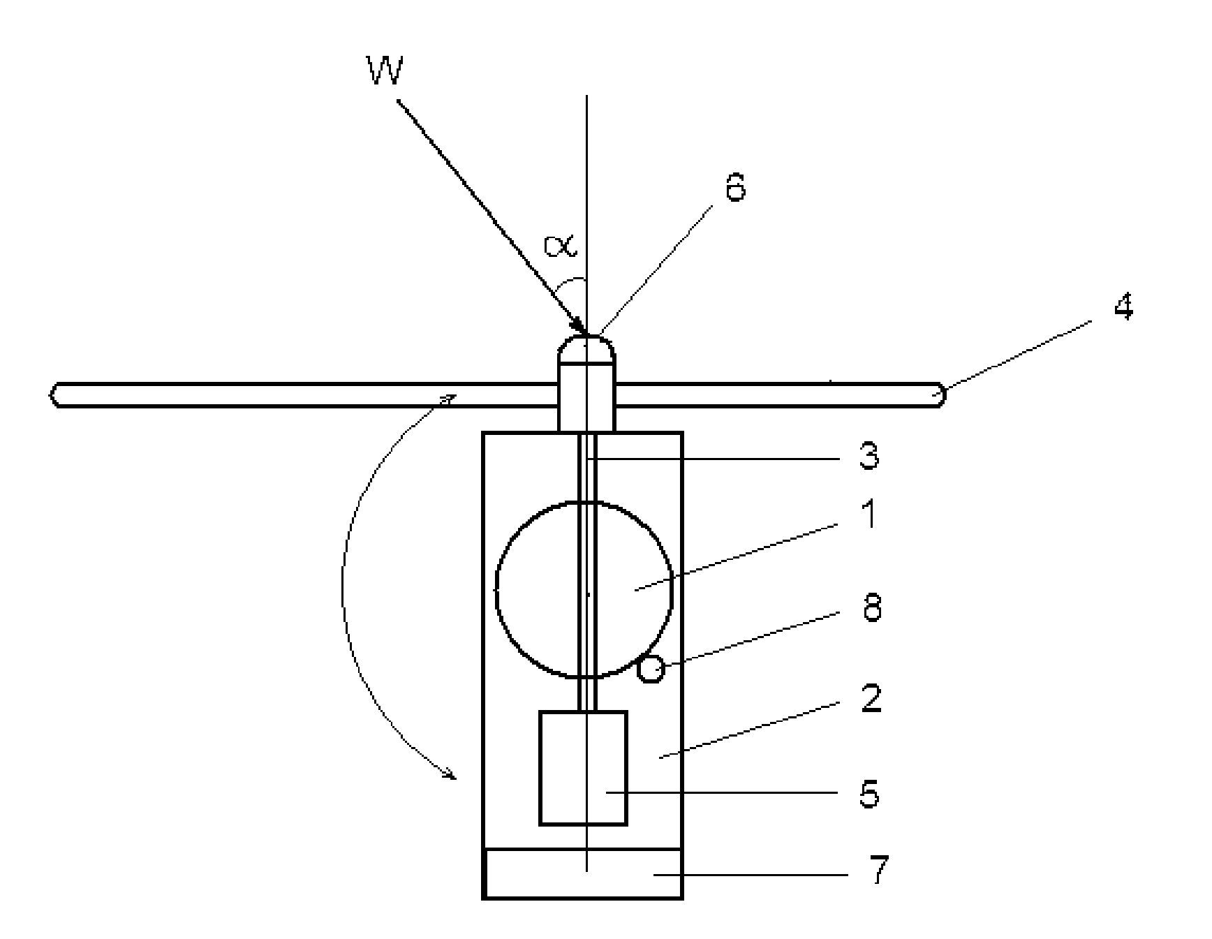
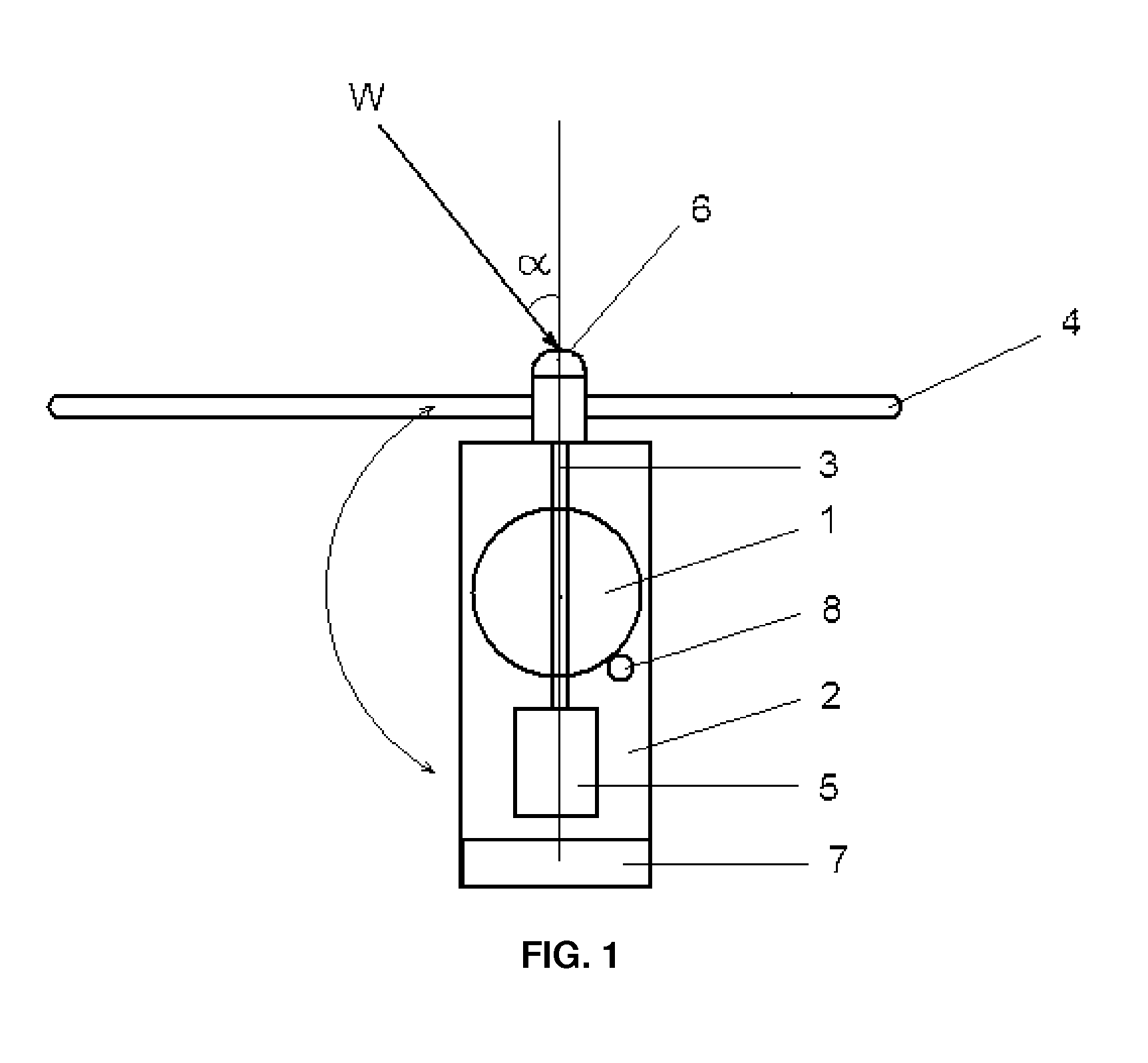
[0038]FIG. 1 shows schematically the wind turbine according to the present invention intended for implementing the method according to the present invention, the said wind turbine comprising the tower 1, on which the rotatable around the vertical axis nacelle 2 is mounted and the rotor shaft 3, rotatable around the horizontal axis and formed by three blades 4 intended for transforming the wind energy into the rotational movement of the rotor shaft in the described embodiment of the invention is installed in the nacelle 2. Generally, the rotor shaft axis deviates from the wind direction W by angle a. The electric generator 5 is mechanically connected to the rotor shaft 3. In order to control the yaw angle of the rotor, the wind turbine is equipped with the blades position sensor 6 with yaw controller 7 and with the nacelle yaw drive 2 (yaw actuator 8) integrated in the closed loop automated control.

[0039]The WT rotor yaw control method is based on the contactless measurement of the c...


PUM


Abstract

The present invention relates to the wind power engineering and to the method of controlling a yaw angle of the wind turbine, equipped with a horizontal rotor shaft as well as to the wind turbine for implementing the method. According to the method of the present invention, the time difference between the time moments when the rotor blades are in the lower vertical position, the said time moments derived from the reference signal of the sensor connected to the rotor shaft, and the time moments when the blades are on one line with the wind direction and the tower, the said time moments_derived from the periodic signal of the spurious amplitude modulation generated by the AC generator and caused by aerodynamic interaction between the blades and the tower, is used as the indication of actual position of the wind turbine rotor relative to the wind direction. The wind turbine of the present invention comprises a yaw controller including the functional units suitable for generating a control signal for rotating a nacelle of wind turbine based on the given time difference in order to compensate the existing yaw error.

Description

RELATED APPLICATIONS[0001]This application claims priority to Patent Cooperation Treaty Application number PCT / UA2011 / 000130, filed on Dec. 27, 2011, which claims priority to Ukrainian patent application number a201106319, filed on May 19, 2011 and incorporated herewith by reference in its entirety.FIELD OF THE INVENTION[0002]The present invention relates to the wind power engineering and to the method of wind turbine yaw angle control, the said wind turbine being equipped with a horizontal rotor shaft, as well as to the wind turbine, being controlled by such a method.BACKGROUND OF THE INVENTION[0003]Wind power engineering is the most dynamically developed among the most perspective directions of using the renewable energy sources and has already become a competitive player on the market of electric energy generation.[0004]The overwhelming majority of the modern wind turbines (WTs) have a three-bladed rotor with a horizontal rotor shaft. Such turbines require a certain mechanism for...

Claims


Application Information

Patent Timeline
IPC IPC(8): F03D7/02F03D9/00
CPCF03D9/002F03D7/0204F03D7/02F03D7/042F03D9/25Y02E10/72F03D17/00
Inventor MYKHAYLYSHYN, VIKTOR
Owner MITA TEKNIK
Why Eureka
Try Eureka