Component-embedded resin substrate

Active Publication Date: 2014-08-07
MURATA MFG CO LTD
View PDF16 Cites 5 Cited by
  • Summary
  • Abstract
  • Description
  • Claims
  • Application Information

AI Technical Summary

Benefits of technology

[0009]Then, an object of the present invention is to provide a component-embedded resin substrate in which occurrence of what is called

Problems solved by technology

Component-embedded resin substrates having an outer geometry other than a rectangle in a planar view are hereinafter referred to as a “substrate of variant shape.” In the substrate of variant shape, in particular, arrangement of an embedded component gives rise to

Method used


Image

  • Component-embedded resin substrate
  • Component-embedded resin substrate
  • Component-embedded resin substrate

Examples


first embodiment

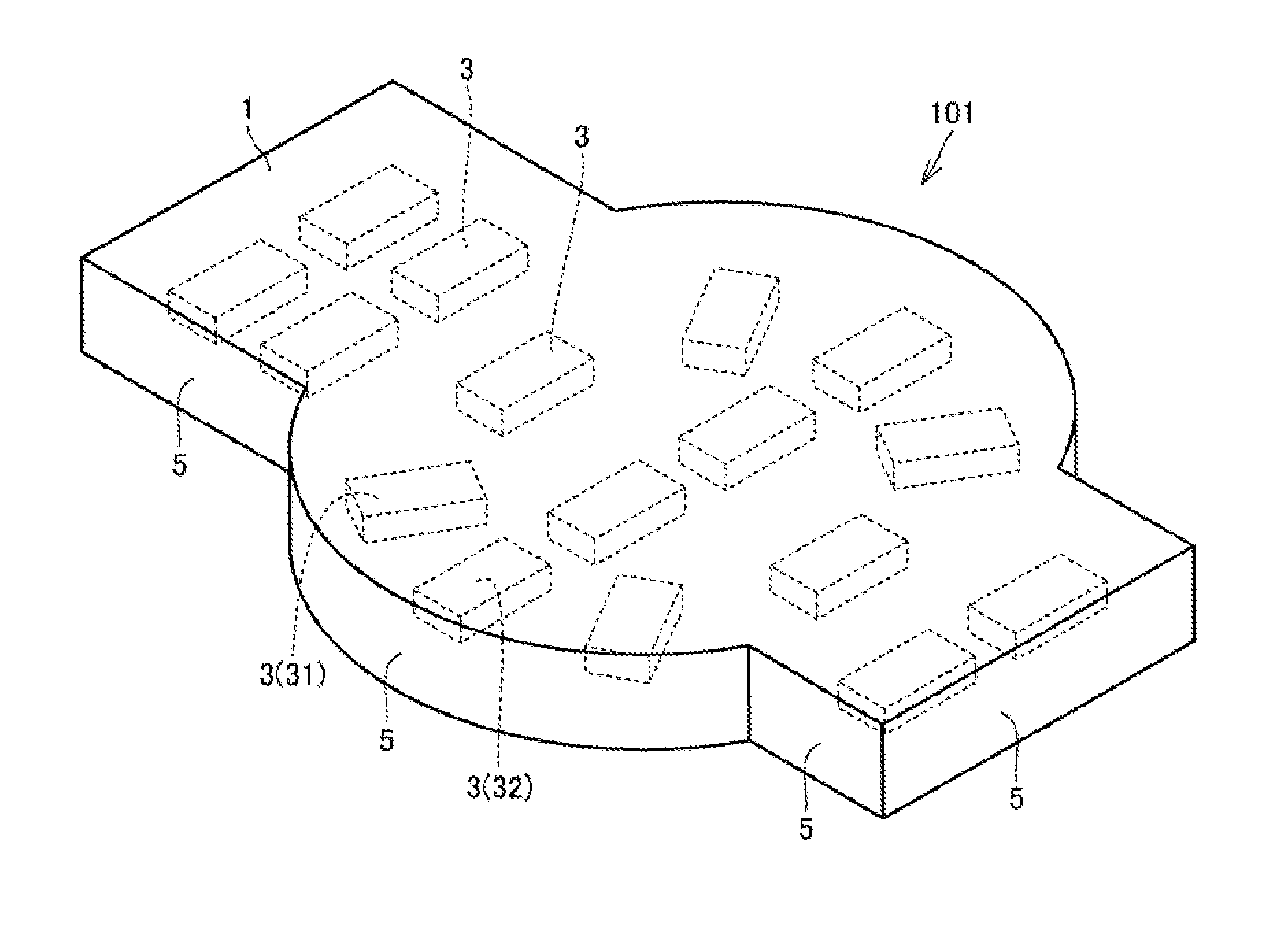
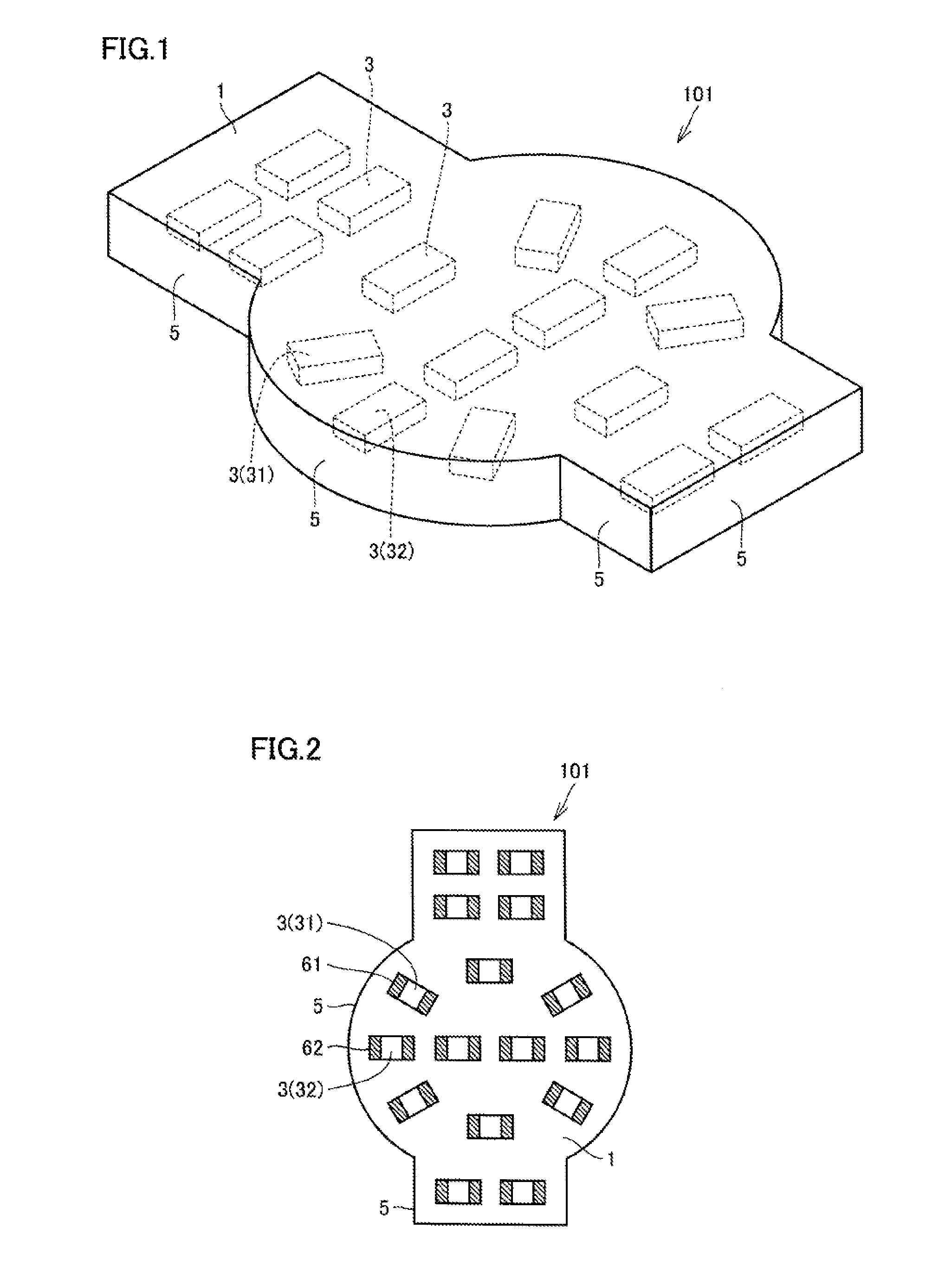
[0046]A component-embedded resin substrate in a first embodiment based on the present invention will be described with reference to FIGS. 1 and 2. Since embedded component 3 is hidden in a resin structure 1 in FIG. 1, any embedded component 3 is drawn with a dashed line. Though resin structure 1 may have already been integrated, it originally includes a plurality of laminated resin layers. FIG. 2 shows a component-embedded resin substrate 101 as seen through in a planar view for description of positional relation of embedded components 3. Therefore, in FIG. 2, embedded component 3 hidden in resin structure 1 is also drawn with a solid line instead of a dashed line. FIGS. 1 and 2 do not show a conductor pattern and a via conductor arranged on a surface or in the inside of resin structure 1, which is also the case with a perspective plan view below.

[0047]As shown in FIG. 1, component-embedded resin substrate 101 in the present embodiment includes resin structure 1 including a pluralit...

second embodiment

[0061]A component-embedded resin substrate in a second embodiment based on the present invention will be described with reference to FIG. 13. FIG. 13 shows with a dashed line, embedded component 3 arranged as hidden in resin structure 1, as it is seen through. Since a surface mount component 8 is arranged on the surface of resin structure 1, it is shown with a solid line. A component-embedded resin substrate 109 in the present embodiment includes the features described in the first embodiment and further additionally includes features below. Component-embedded resin substrate 109 in the present embodiment includes one or more surface mount components 8 placed on the surface of resin structure 1 and having a rectangular shape with a long side 81 and a short side 82 when viewed in a planar view. Embedded component 3 located at a position closest to surface mount component 8 when viewed in a steric view is defined as a “closest embedded component”35. Closest embedded component 35 is in...


PUM


Abstract

A component-embedded resin substrate includes a resin structure including a plurality of laminated resin layers and having an end surface surrounding an outer periphery of the resin layers and a plurality of embedded components arranged as embedded in the resin structure. The plurality of embedded components include a first embedded component and a second embedded component. When viewed in a planar view, the first embedded component has a first outer side extending along a portion of an end surface 5 closest to the first embedded component. When viewed in a planar view, the second embedded component has a second outer side extending along a portion of the end surface closest to the second embedded component. When viewed in a planar view, the outer side is oblique to the second outer side.

Description

BACKGROUND OF THE INVENTION[0001]1. Field of the Invention[0002]The present invention relates to a component-embedded resin substrate.[0003]2. Description of the Related Art[0004]FIG. 31 shows one example of a component-embedded resin substrate based on the conventional art. In this example, in the inside of a component-embedded resin substrate 901, a resin layer 2 serving as an insulating layer surrounds an outer periphery of an embedded component 3. Component-embedded resin substrate 901 contains a plurality of via conductors 6 and a plurality of conductor patterns 7. As shown in FIG. 32, embedded component 3 is in a parallelepiped shape and has electrodes 3a, 3b at respective opposing end portions. As shown in FIG. 31, via conductors 6n are connected to electrodes 3a, 3b of embedded component 3, respectively.[0005]Japanese Patent Laying-Open No. 2006-73763 (PTD 1) describes one example of a method of manufacturing a component-embedded resin substrate based on the conventional art...

Claims


Application Information

Patent Timeline
IPC IPC(8): H05K1/18
CPCH05K1/183H05K1/0298H05K2201/10507H05K2201/0195H05K1/0306H01L23/49822H01L23/50H01L24/95H01L2224/16225H01L2924/19105H05K1/186H05K3/4614H05K3/4697H05K2201/09027H05K2201/10636H01L2924/12042Y02P70/50H01L2924/00
Inventor SAKAI, NORIOOTSUBO, YOSHIHITO
Owner MURATA MFG CO LTD
Why Eureka
Try Eureka