
Dual-bearing reel

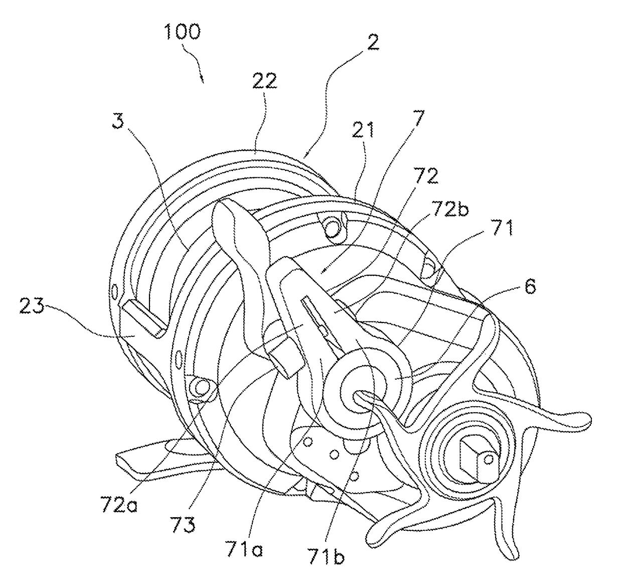
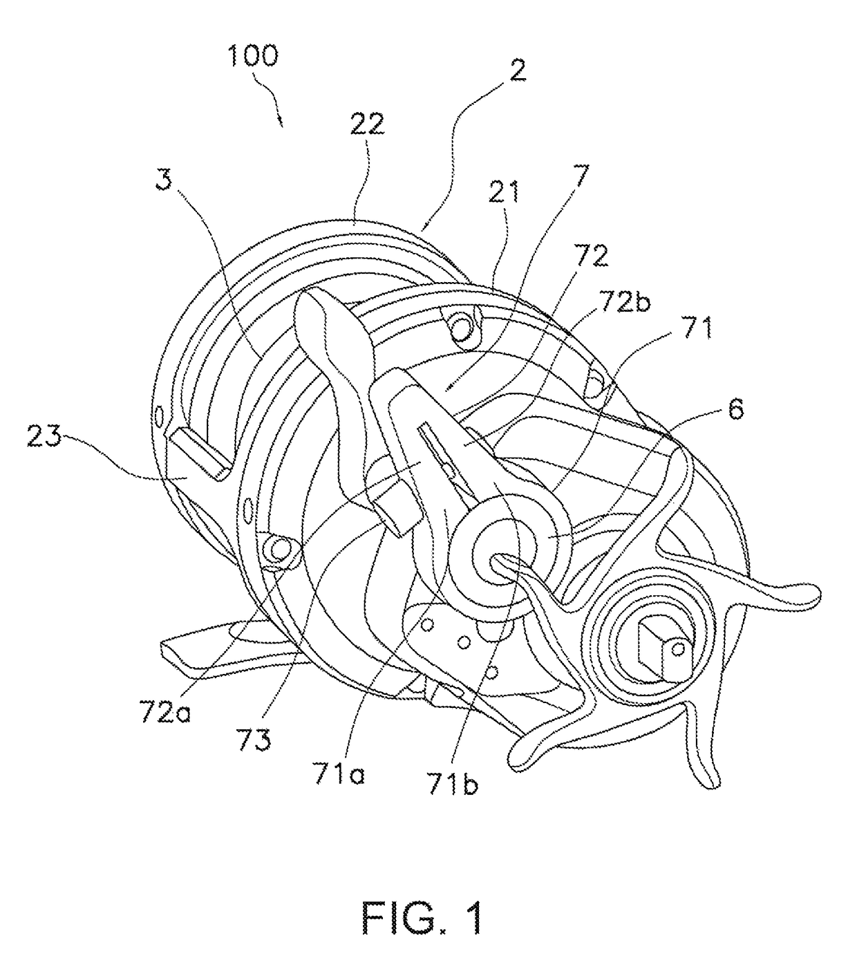
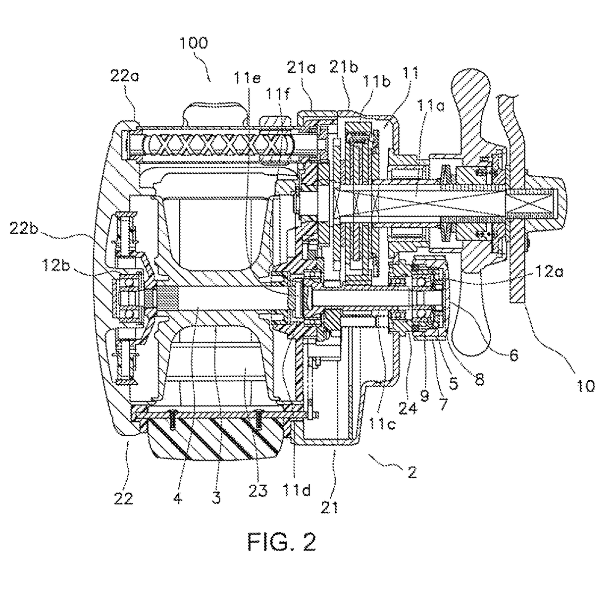
a reel and double-bearing technology, applied in the direction of reels, shafts and bearings, rotary bearings, etc., can solve the problems of difficult operation of the operating lever and the direction of the angler, and achieve the suppression of the rotational speed of the spool shaft, prevent backlash, and suppress the generation of rotational resistance

Active Publication Date: 2017-11-07
SHIMANO INC
View PDF4 Cites 2 Cited by
  • Summary
  • Abstract
  • Description
  • Claims
  • Application Information

AI Technical Summary

Benefits of technology

The present invention is a dual-bearing reel with an easy-to-operate operating lever. The reel has a mechanism that prevents excessive backlash during casting by slowing down the rotation of the spool shaft. On the other hand, during reeling, the spool shaft can rotate smoothly without generating resistance. The operating lever is positioned in a way that makes it easy for the operator to use.

Problems solved by technology

When adjusting to an appropriate braking force using the operating lever in the dual-bearing reel described above, there are cases in which the operating lever is extended in a direction that is difficult to operate for an angler.
For example, if the operating lever is extended in a direction toward the fishing rod mounting side, the operating lever can be difficult for the angler to operate.

Method used


Image

  • Dual-bearing reel
  • Dual-bearing reel
  • Dual-bearing reel

Examples


modified example 1

[0072]In the above-described embodiment, the adjustment member 6 brakes the rotation of the spool shaft 4 via the one-way clutch 5, but may omit the one-way clutch 5 and directly brake the rotation of the spool shaft 4. For example, as shown in FIG. 4, the first friction plate 8 may contact the end surface 4a of the spool shaft 4.

modified example 2

[0073]As shown in FIG. 5, the adjustment member 6 according to the second modified example comprises multiple recesses 64. Each recess 64 is formed on the outer perimeter surface of the cylindrical portion 62. The recesses 64 are disposed at intervals from each other in the circumferential direction. The operating lever 7 may be attached to each recess 64. Specifically, the operating lever 7 is screwed to each recess 64. Further, as shown in FIG. 6, the recesses 64 can be arranged in a staggered manner in the circumferential direction. According to the above, the position of the operating lever 7 in the circumferential direction becomes adjustable at a finer pitch.

modified example 3

[0074]As shown in FIG. 7, in a dual-bearing reel according to the third modified example, the adjustment member 6 comprises multiple recesses 64 on the outer perimeter surface thereof. Then, the cover portion 71 of the operating lever 7 is attached so as to cover the outer perimeter surface of the adjustment member 6. It is possible to prevent foreign objects from clogging the recesses 64 by the cover portion 71 covering the recesses 64. Further, the cover portion 71 and the lever portion 72 are separate members from each other. The lever portion 72 is attached to the cover portion 71 by being screwed to the cover portion 71. Further, one end of the lever portion 72 extends through the cover portion 71 and engages the recesses 64.


PUM


Abstract

A dual-bearing reel, includes a reel body, a spool, a spool shaft, an adjustment member, and an operating lever. The spool is rotatable relative to the reel body. The spool shaft is configured to integrally rotate with the spool. The adjustment member is attached to the reel body and configured to adjust a braking force that brakes the rotation of the spool shaft. The operating lever is detachably attached to the adjustment member so as to extend in a radial direction, and configured to be positionally adjusted in a circumferential direction relative to the adjustment member.

Description

CROSS-REFERENCE TO RELATED APPLICATIONS[0001]This application claims priority based on Japanese Patent Application No. 2015-107017, filed in the Japan Patent Office on May 27, 2015, the contents of each of which is hereby incorporated herein by reference.BACKGROUND[0002]Field of the Invention[0003]The present invention relates to a dual-bearing reel.[0004]Background Information[0005]In the dual-bearing reel disclosed in Japanese Laid-Open Patent Publication No. 1997-275861, an operating lever is pivotably attached to a reel body, in order to facilitate the operation, of a casting control mechanism. The braking force with respect to the spool shaft can be adjusted by pivoting the operating lever.SUMMARY[0006]When adjusting to an appropriate braking force using the operating lever in the dual-bearing reel described above, there are cases in which the operating lever is extended in a direction that is difficult to operate for an angler. For example, if the operating lever is extended i...

Claims


Application Information

Patent Timeline
Patent Type & Authority Patents(United States)
IPC IPC(8): A01K89/015A01K89/0155F16C19/06F16C19/54
CPCA01K89/0155F16C19/54F16C19/06
Inventor NIITSUMA, AKIRAIKUTA, TAKESHITAKECHI, KUNIOTAKAMATSU, TAKUJIHIRAOKA, HIROKAZU
Owner SHIMANO INC
Learn More