Polling Beacon

a technology of polling beacons and beacons, applied in the field of polling beacons, can solve the problem that the wi-fi device cannot remain associated with the second wireless ap in the second bss network, and achieve the effect of reducing the number of poles and avoiding the poles

a technology of polling beacons and beacons, applied in the field of polling beacons, can solve the problem that the wi-fi device cannot remain associated with the second wireless ap in the second bss network, and achieve the effect of reducing the number of poles and avoiding the poles

US20140241226A1Active Publication Date: 2014-08-28QUALCOMM INC

Image

  • Polling Beacon
  • Polling Beacon
  • Polling Beacon

Examples


Embodiment Construction

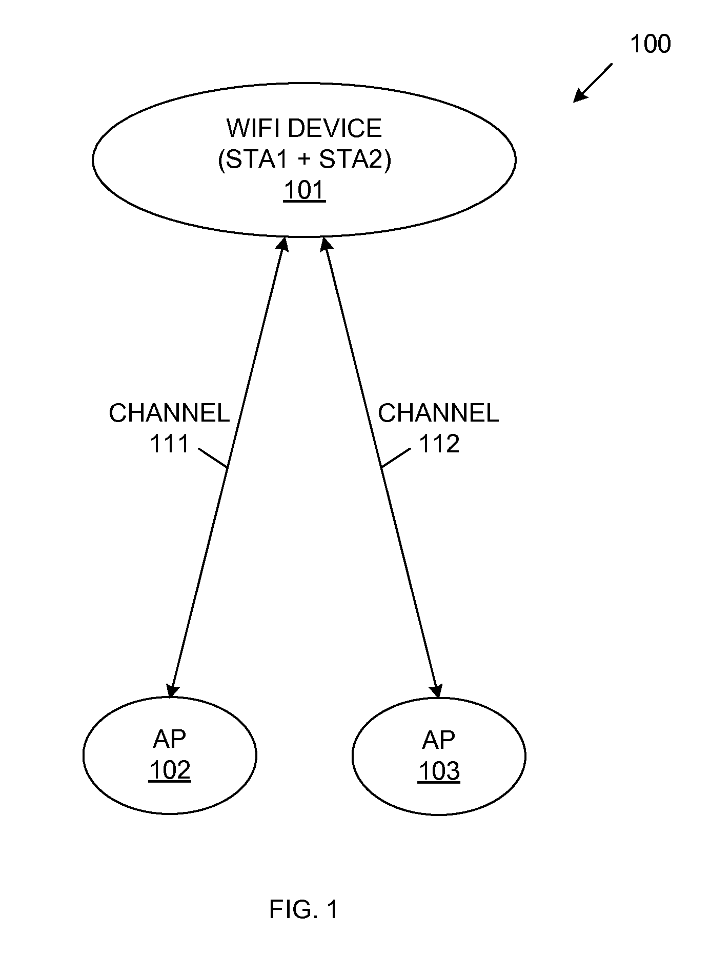
[0016]FIG. 1 is a block diagram of a Wi-Fi system 100, which includes Wi-Fi device 101 and wireless access points (APs) 102 and 103. Wi-Fi device 101 is connected to a first BSS network that includes wireless AP 102, and also participates in a second BSS network that includes wireless AP 103. More specifically, Wi-Fi device 101 operates as a station (STA1) connected to wireless AP 102 in a first channel 111, and also operates as a station (STA2) in a separate second channel 112.

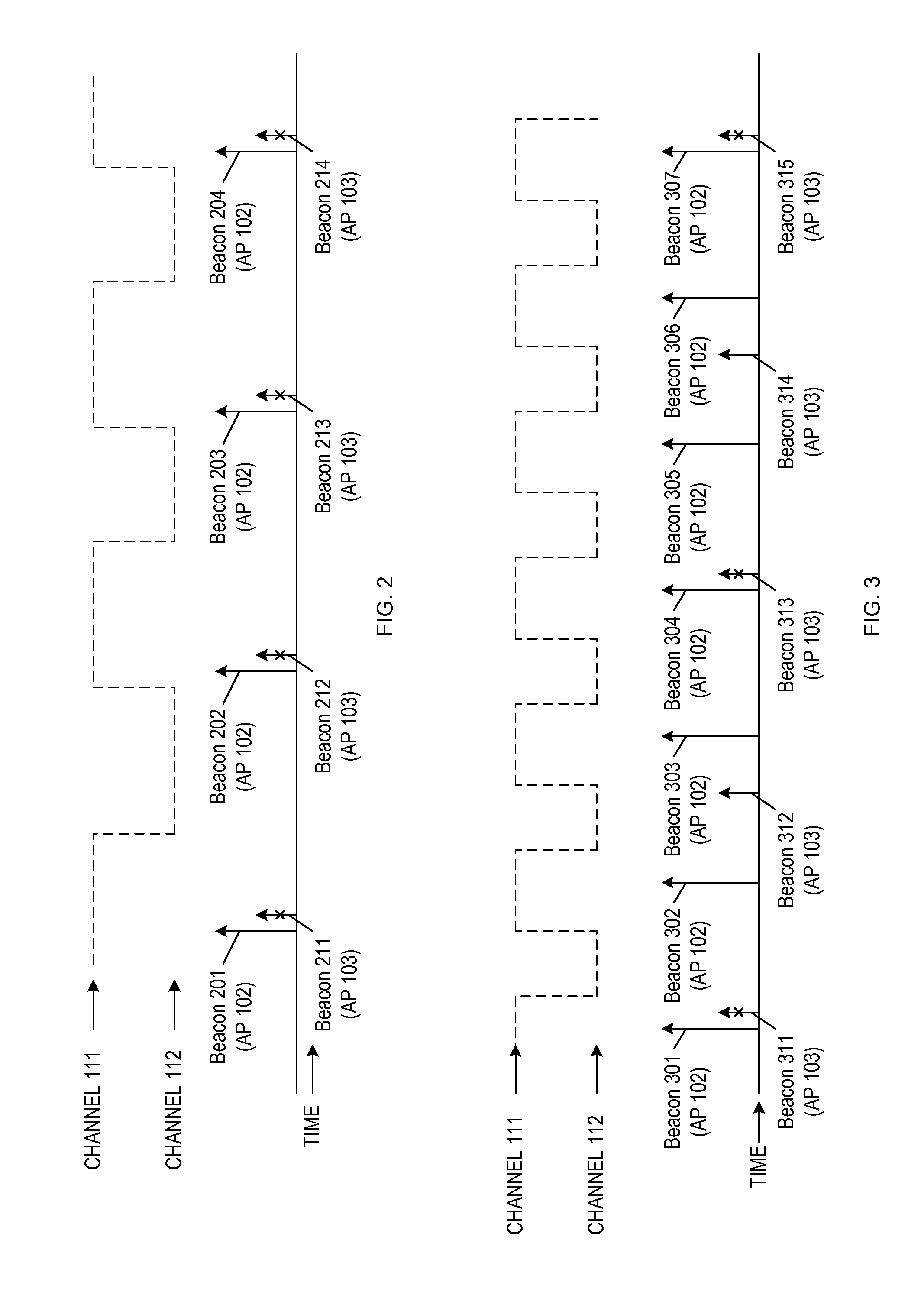
[0017]Wi-Fi device 101 typically operates in a ‘Wi-Fi Power Save Mode’ in order to minimize power consumption, wherein the Wi-Fi device 101 alternately operates in a low-power sleep state and a high-power active state. Within the first BSS network, Wi-Fi device 101 periodically wakes up (transitions from the sleep mode to the active state) at predetermined target beacon transmission times (TBTTs) to receive beacon frames (i.e., beacons) broadcast from the associated wireless AP 102 on the first channel 111. T...


PUM


Abstract

Beacon-poll frames are transmitted from a station (STA) to a wireless AP in an opportunistic manner. In response to receiving a beacon-poll frame, the wireless AP transmits a unicast beacon frame to the STA, thereby eliminating the need for the STA to periodically wake up to receive broadcast beacon frames from the AP. The wireless AP may transmit the unicast beacon frame at a higher speed than a conventional broadcast beacon frame. As a result, the time that the STA must be awake to receive the unicast beacon frame is significantly less than the time that the STA must be awake to receive a conventional broadcast beacon frame, thereby resulting in significant power savings within the STA. The wireless AP may aggregate downlink (DL) data packets to be transmitted to the STA with the unicast beacon frame, resulting in further power savings within the STA.

Description

FIELD OF THE INVENTION[0001]The present invention relates to the use of a polling beacon to save power in a wireless communication system.RELATED ART[0002]In a Wi-Fi system, a Wi-Fi device might be simultaneously connected to a first BSS (basic service set) network as a station (STA) (or a Wi-Fi direct client) in a first channel, and also participate in a second BSS network as a station (STA) (or Wi-Fi direct client) in a second channel, different than the first channel. In order to participate in both the first and second BSS networks, the Wi-Fi device must be able to receive beacon frames that are periodically transmitted from wireless access points (APs) (or Wi-Fi direct group owners (GOs)) in both the first and second BSS networks. Thus, within the first BSS network, the Wi-Fi device will periodically wake up at a first set of predetermined target beacon transmission times (TBTTs) to receive beacon frames (i.e., beacons) broadcast from a first associated wireless AP (or Wi-Fi di...

Claims


Application Information

Patent Timeline
28 Aug 2014
Publication
US20140241226A1
IPC
H04W52/02
CPC
H04W52/0229; H04W48/12; H04W48/14; H04W52/0216; Y02D30/70
Inventors
JIA, ZHANFENG; HOMCHAUDHURI, SANDIP