Pen pressure detecting module and position indicator

a technology of position indicator and pressure detecting module, which is applied in the field of position indicators, can solve the problems of increasing the number of assembly man-hours, complex structure, and difficulty in further thinning the position indicator, and achieves the effect of simple constitution, suitable for thinning and mass production

Active Publication Date: 2015-02-05
WACOM CO LTD
View PDF2 Cites 21 Cited by
  • Summary
  • Abstract
  • Description
  • Claims
  • Application Information

AI Technical Summary

Benefits of technology

[0037]According to the present disclosure, it is possible to provide a pen pressure detecting module that has a very simple constitution and which is suitable for thinning and is also suitable for mass production.

Problems solved by technology

This also results in a complex structure.
However, because there is a limit to the thinning of the constitution of the pen pressure detecting mechanism part in related art, it is difficult to further thin the position indicator.
Hence, the work of inserting all of the plurality of parts forming the pen pressure detecting mechanism part into the hollow portion of the holder and arranging the parts within the hollow portion of the holder while considering alignment of all of the plurality of parts in the axial direction and a direction orthogonal to the axial direction involves difficulty and increases the number of man-hours required for assembly.
The pen pressure detecting mechanism part in related art is thus unsuitable for mass production.

Method used


Image

  • Pen pressure detecting module and position indicator
  • Pen pressure detecting module and position indicator
  • Pen pressure detecting module and position indicator

Examples


first embodiment

Modification of First Embodiment

[0156]Other Examples of Engagement Relation of Core Body Main Body Portion 41 with Recessed Hole 7311 of Locking Member 731 of Inside Holder 73

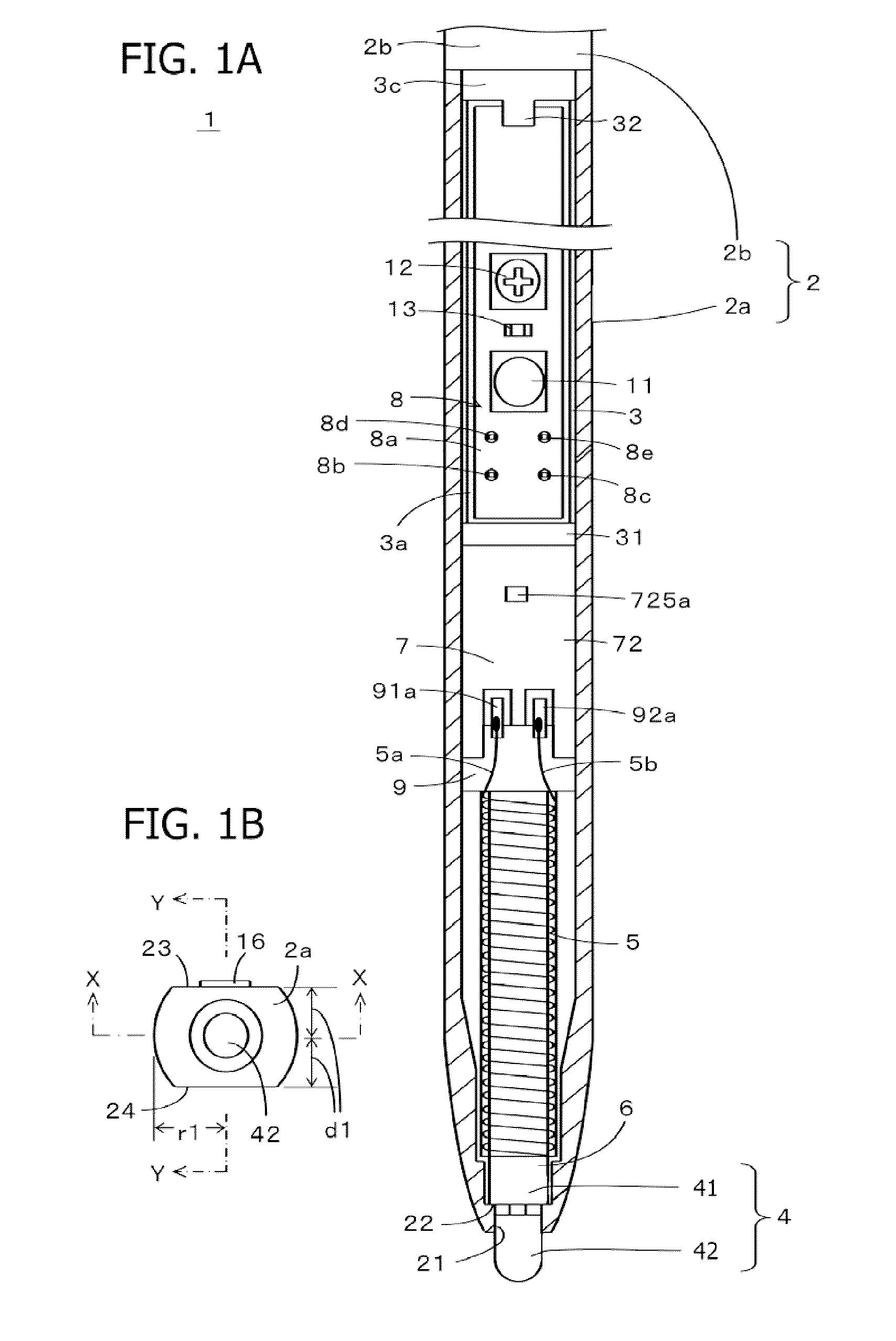
[0157]In the above-described first embodiment, the core body main body portion 41 of the core body 4 is provided with the annular projecting portion 411, and the recessed hole 7311 of the locking member 731 of the inside holder 73 is provided with the annular projecting portion 7312. The annular projecting portion 411 of the core body main body portion 41 and the annular projecting portion 7312 of the recessed hole 7311 are engaged with each other when the annular projecting portion 411 of the core body main body portion 41 goes over the annular projecting portion 7312 of the recessed hole 7311. However, the engagement of the core body main body portion 41 with the locking member 731 is not limited to the engagement of the projecting portions with each other as in the above-described example.

[0158]Specifically,...

second embodiment

Modifications of Second Embodiment

[0187]Also in the second embodiment, as in the foregoing first embodiment, modifications can be made to the engagement relation between the pressure transmitting member and the holder.

[0188]Specifically, FIGS. 14A and 14B correspond to the modifications in FIGS. 9A and 9B in the first embodiment. FIG. 14A represents a case where an annular dent portion 412 is formed in the core body main body portion 41 in place of the annular projecting portion 411. In the present example, as in the first embodiment, the annular dent portion 412 is fitted to the annular projecting portion 7411′ of the recessed hole 741. Thus, as in the first embodiment, the depth of the recessed hole 741 is smaller than that of the recessed hole 741 in the example of FIG. 13.

[0189]In the second embodiment, the core body main body portion 41 itself is displaced so as to press the first electrode 81 of the semiconductor chip 80, whereas the holder 74 is fixed to the board holder 3, a...

third embodiment

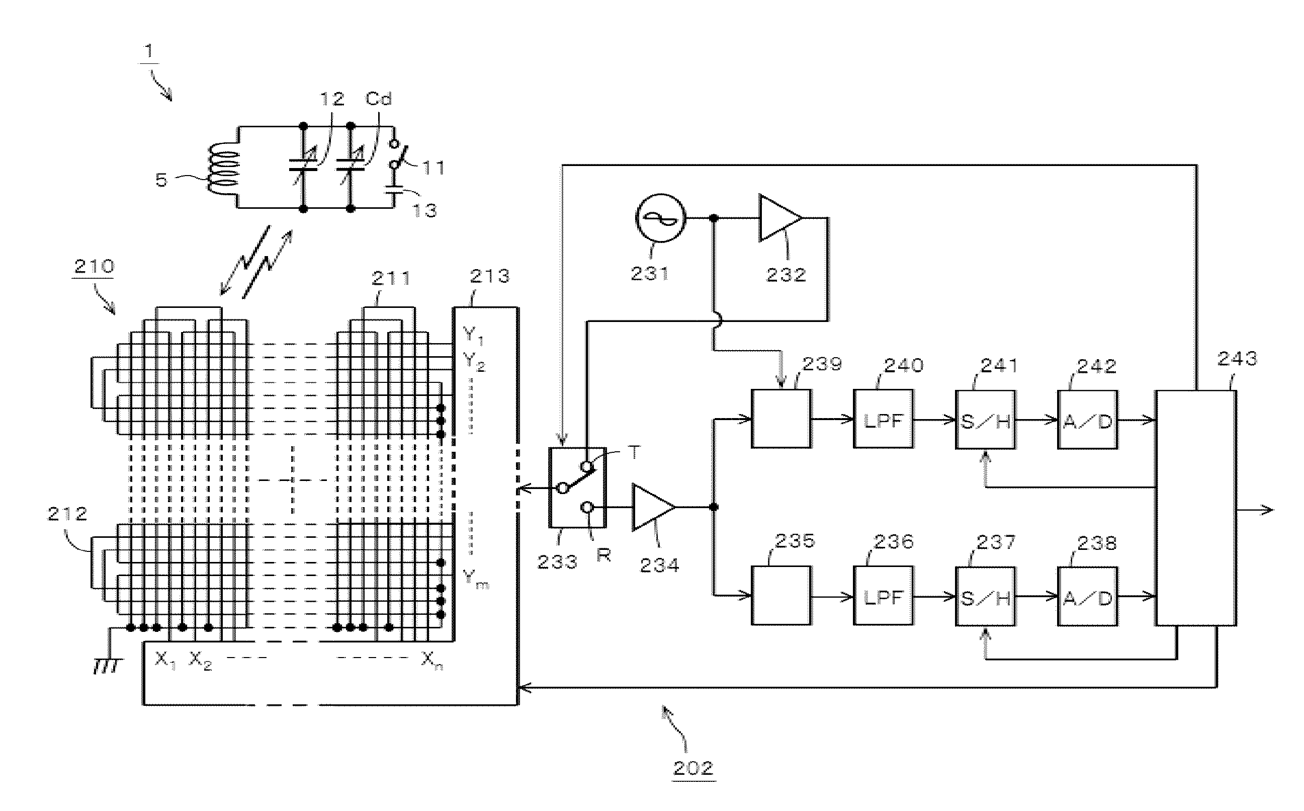
[0200]The above description has been made in a case where the present disclosure is applied to an electromagnetic induction type position indicator. However, the present disclosure is applicable also to a capacitance type position indicator.

[0201]FIG. 17 is a diagram showing an embodiment of a capacitance type position indicator according to the present disclosure. The capacitance type position indicator 1B in the present example has a structure formed by screwing a sleeve 1001 to a tip side of a case 1000 formed of a conductor such as a metal, for example. An opening for exposing a core body 1002 to the outside is provided in the sleeve 1001. A tip of the core body 1002 is formed so as to project from the opening to the outside.

[0202]In this case, the core body 1002 is formed of a conductor of a metal, for example. A tip portion of the core body 1002 is covered with an elastic cap 1003 formed of a conductive member. The inside of the sleeve 1001 is covered with a conductive member ...


PUM


Abstract

Disclosed herein is a pen pressure detecting module housed in a position indicator, the position indicator having a pen shape and being capable of detecting a pressure applied to a tip portion of the position indicator. The pen pressure detecting module includes a pressure sensing device, a first holder, and a second holder. The pressure sensing device senses the pressure based on a change in a capacitance formed between a first electrode and a second electrode disposed so as to be opposed to each other, which capacitance changes so as to correspond to the pressure that is transmitted to the first electrode. The second holder is housed in the first holder, and the pressure sensing device is disposed so as to sense the pressure applied to the second holder. An engaging portion engaged with a pressure transmitting member that transmits the pressure is formed in the second holder.

Description

BACKGROUND[0001]1. Technical Field[0002]The present disclosure relates to a position indicator having a pen pressure detecting function, the position indicator being used in conjunction with a position detecting device, a pen pressure detecting module used in the position indicator, and a position indicator using the pen pressure detecting module.[0003]2. Description of the Related Art[0004]A position input device has recently been used as an input device for a tablet type PC (personal computer), a portable apparatus, or the like. This position input device includes, for example, a position indicator formed in the shape of a pen and a position detecting device having an input surface on which pointing operations and the input of characters, figures, and the like are performed by using the position indicator.[0005]In related art, as a pen type of position indicator of this kind, a position indicator for an electromagnetic induction type of position detecting device is well known. The...

Claims


Application Information

Patent Timeline
Patent Type & Authority Applications(United States)
IPC IPC(8): G06F3/0354
CPCG06F3/03545G06F3/044G06F3/0445
Inventor ITO, MASAMITSUKAMIYAMA, RYOJIYAMASHITA, SHIGERU
Owner WACOM CO LTD
Why Eureka
Try Eureka