Intermediate electrical connector and electrical connector assembled component

Active Publication Date: 2015-03-19
HIROSE ELECTRIC GROUP
View PDF1 Cites 14 Cited by
  • Summary
  • Abstract
  • Description
  • Claims
  • Application Information

AI Technical Summary

Benefits of technology

[0030]According to the third aspect of the present invention, similarly to the first and the second aspect of the present invention, in a state that the connectors are fitted, the contact parts where the contact portions of the signal terminals and the mating contact portions of the mating signal terminals contact are shielded from the both sides in the blade's thickness direction by the second ground plate and the mating ground plate. Therefore, signals are transmitted without influence of noises from outside. In addition, similarly to the first and the second aspects of the present invention, the second ground plate and the ground terminals are provided as separate members. Therefore, it is easy to adjust the impedance by forming the parts of the ground plates, which correspond to the signal contact portions of the signal terminals, in preferred shapes.
[0031]According to a fourth aspect of the present invention, the mating connectors are provided in rows arranged corresponding to the intermediate connecting members of the relay electrical connector, which is arranged in the blade's thickness direction. The plurality of mating connectors is connected to each other by connecting members or joining members. The connecting members extend in the arrangement direction of the plurality of mating connectors. The connecting members are carriers that can be connected to the plurality of mating ground plates. The carriers can connect the plurality of mating connectors via the mating ground plates respectively held by the housings of the mating connectors without being cut off from the mating ground plates.
[0032]As described above, according to the electrical connector assembled component, the plurality of mating connectors is joined by the connecting members. The connecting members are connected to the mating gr

Problems solved by technology

Therefore, there is concern that signal transmission at the contact parts could be affected by noises from outside.
Therefore, it is not easy to provide a

Method used


Image

  • Intermediate electrical connector and electrical connector assembled component
  • Intermediate electrical connector and electrical connector assembled component
  • Intermediate electrical connector and electrical connector assembled component

Examples


Example

[0052]Hereunder, embodiments of the present invention will be described with reference to the accompanying drawings.

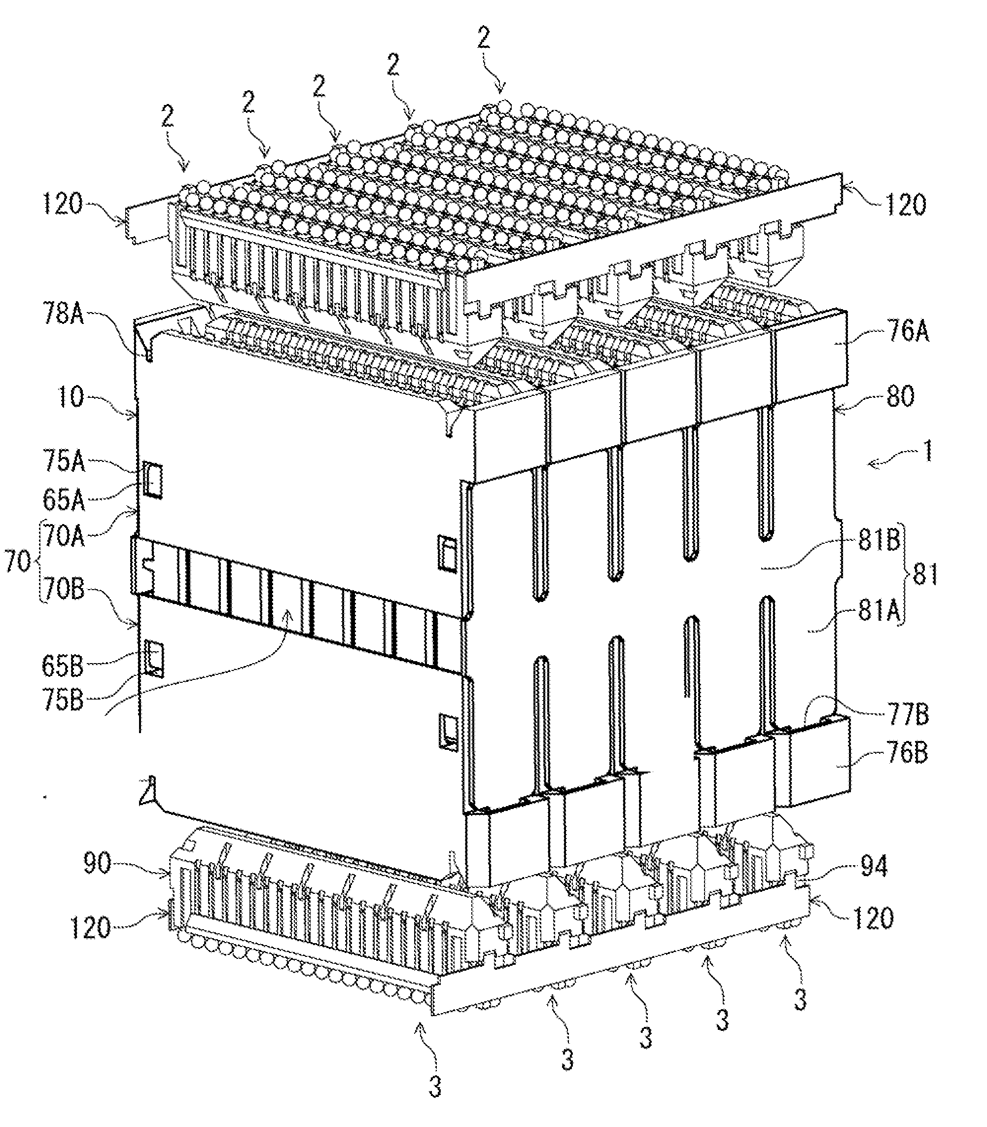
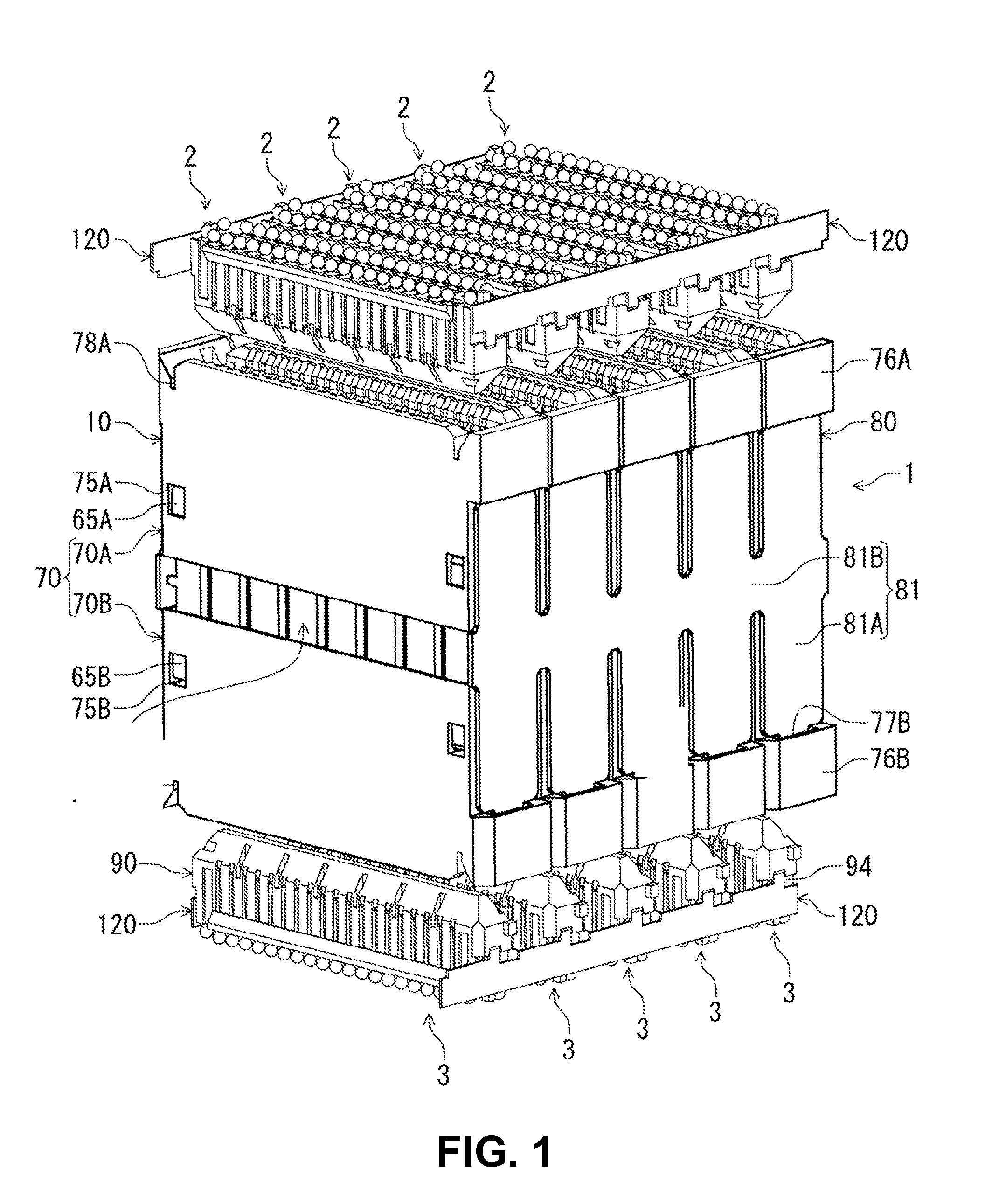
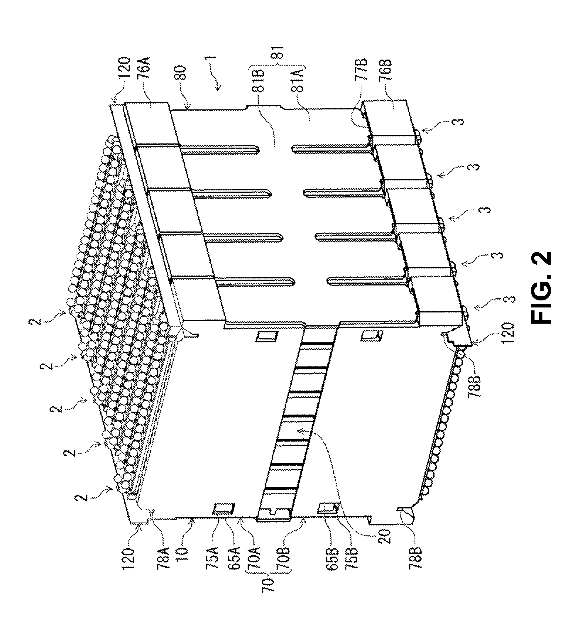
[0053]FIG. 1 is a perspective view showing an intermediate electrical connector according to the embodiment of the invention, which shows with mating connectors thereof, in a state before fitting to the intermediate electrical connector. FIG. 2 is a perspective view showing the intermediate electrical connector of FIG. 1 and the mating connectors thereof in their fitted states.

[0054]As shown in FIG. 1, to the intermediate electrical connector 1 of the embodiment (hereinafter simply referred to as “relay connector 1”), connected are mating connecting bodies, mating connectors 2 and 3, from thereabove and thereunder, respectively. The intermediate electrical connector relays and connects between the mating connectors 2 and 3. The mating connectors 2 and 3 are electrical connectors to be used on circuit boards, have the same shapes, and are to be connected to circuit boar...


PUM


Abstract

An intermediate electrical connector to be connected to a mating connecting member includes an intermediate connecting member; and a blade disposed in the intermediate connecting member. The blade includes a first ground plate, a second ground plate, a base member, a signal terminal, and a ground terminal. The signal terminal includes a first contact portion and a first connecting portion connected to the first contact portion. The ground terminal includes a second contact portion and a second connecting portion connected to the second contact portion. The first ground plate is situated on one side of the blade over the first connecting portion and the second connecting portion. The second ground plate is situated on an opposite side of the blade over the first connecting portion, the second connecting portion, the first contact portion, and the second contact portion.

Description

BACKGROUND OF THE INVENTION AND RELATED ART STATEMENT[0001]The present invention relates to an intermediate electrical connector for connecting to a mating connecting member, which may include a mating connector or a circuit board. The present invention also relates to an electrical connector assembled component equipped with the intermediate electrical connector and the mating connector thereof.[0002]As a conventional connector and a conventional electrical connector assembled component of this type, for example, Patent Reference has disclosed a conventional intermediate electrical connector.Patent Reference: United States Patent Application Publication No. 2012 / 0214343 [0003]According to Patent Reference, the conventional electrical connector assembled component is mounted on a circuit board that forms a horizontal surface, and is fitted and connected to a mating connector from a side of the conventional intermediate electrical connector. Here, the mating connector includes an ele...

Claims


Application Information

Patent Timeline
IPC IPC(8): H01R13/652
CPCH01R13/652H01R12/707H01R12/7082H01R13/518H01R13/6582H01R13/6586
Inventor TAMAI, NOBUHIRO
Owner HIROSE ELECTRIC GROUP
Why Eureka
Try Eureka