Wheel angle adjustment apparatus for automobile suspension system

Active Publication Date: 2006-06-29
DONG HEE IND
View PDF8 Cites 24 Cited by
  • Summary
  • Abstract
  • Description
  • Claims
  • Application Information

AI Technical Summary

Benefits of technology

[0015] Accordingly, the present invention has been made keeping in mind the above problems occurring in the prior art, and an object of the present invention is to provide a wheel angle adj

Problems solved by technology

However, the conventional torsion beam suspension system does not have a link serving to adjust the wheel alignment between the wheels and the automobile body, unlike other suspension systems (for example, multi-link suspension system).
Therefore, the toe angle and camber angle, set when manufacturing an automobile, can

Method used


Image

  • Wheel angle adjustment apparatus for automobile suspension system
  • Wheel angle adjustment apparatus for automobile suspension system
  • Wheel angle adjustment apparatus for automobile suspension system

Examples


Example

[0026] Reference now should be made to the drawings, in which the same reference numerals are used throughout the different drawings to designate the same or similar components.

[0027] Hereinafter, a preferred embodiment of the present invention will be explained in detail with reference to the attached drawings.

[0028]FIG. 3 is a torsion beam suspension system having a wheel angle adjustment apparatus is according to the preferred embodiment of the present invention. FIG. 4 is an exploded perspective view showing the portion R2 of FIG. 3 from a different angle. FIG. 5 is a sectional view taken along the line B-B of FIG. 3. FIG. 6 is a sectional view taken along the line C-C of FIG. 3.

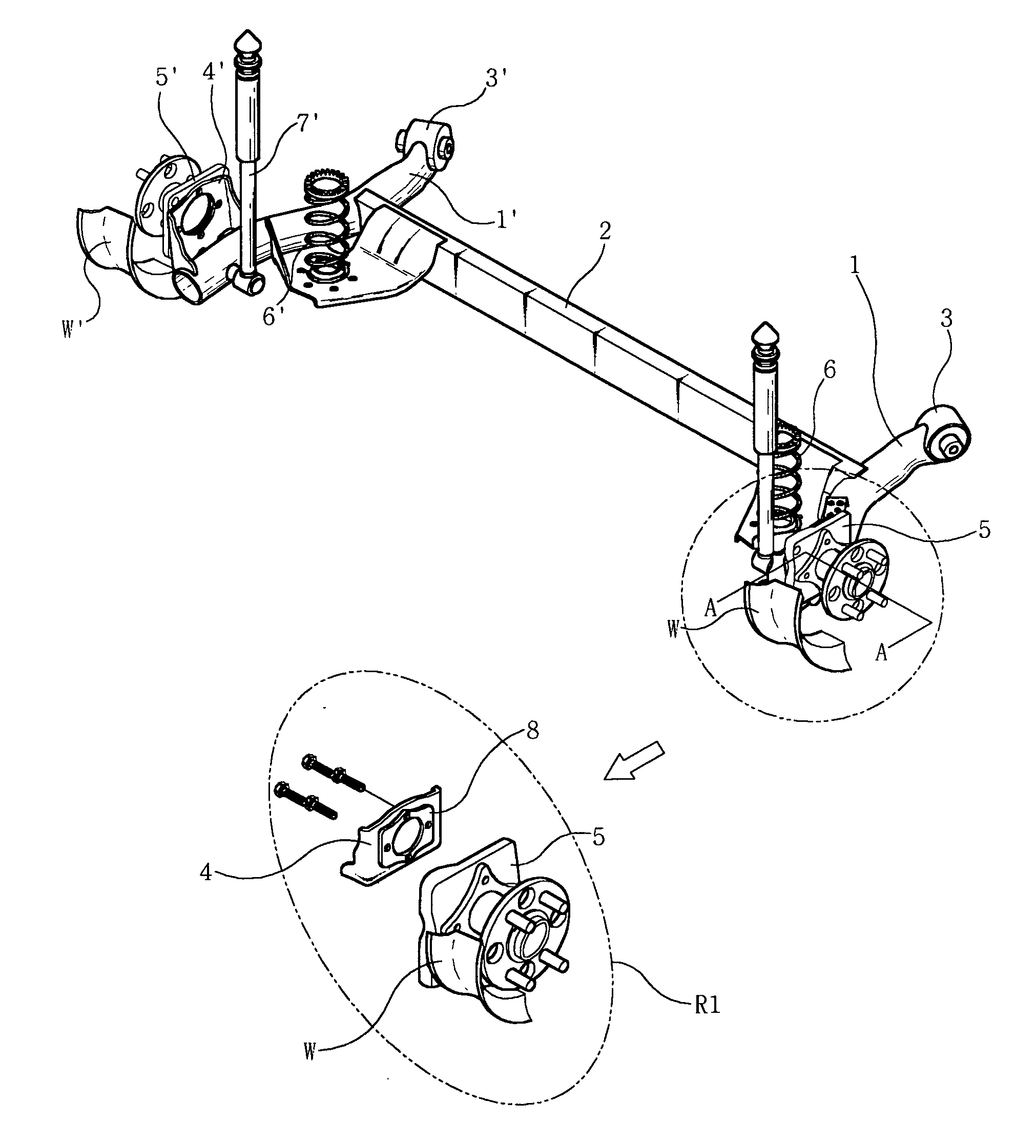
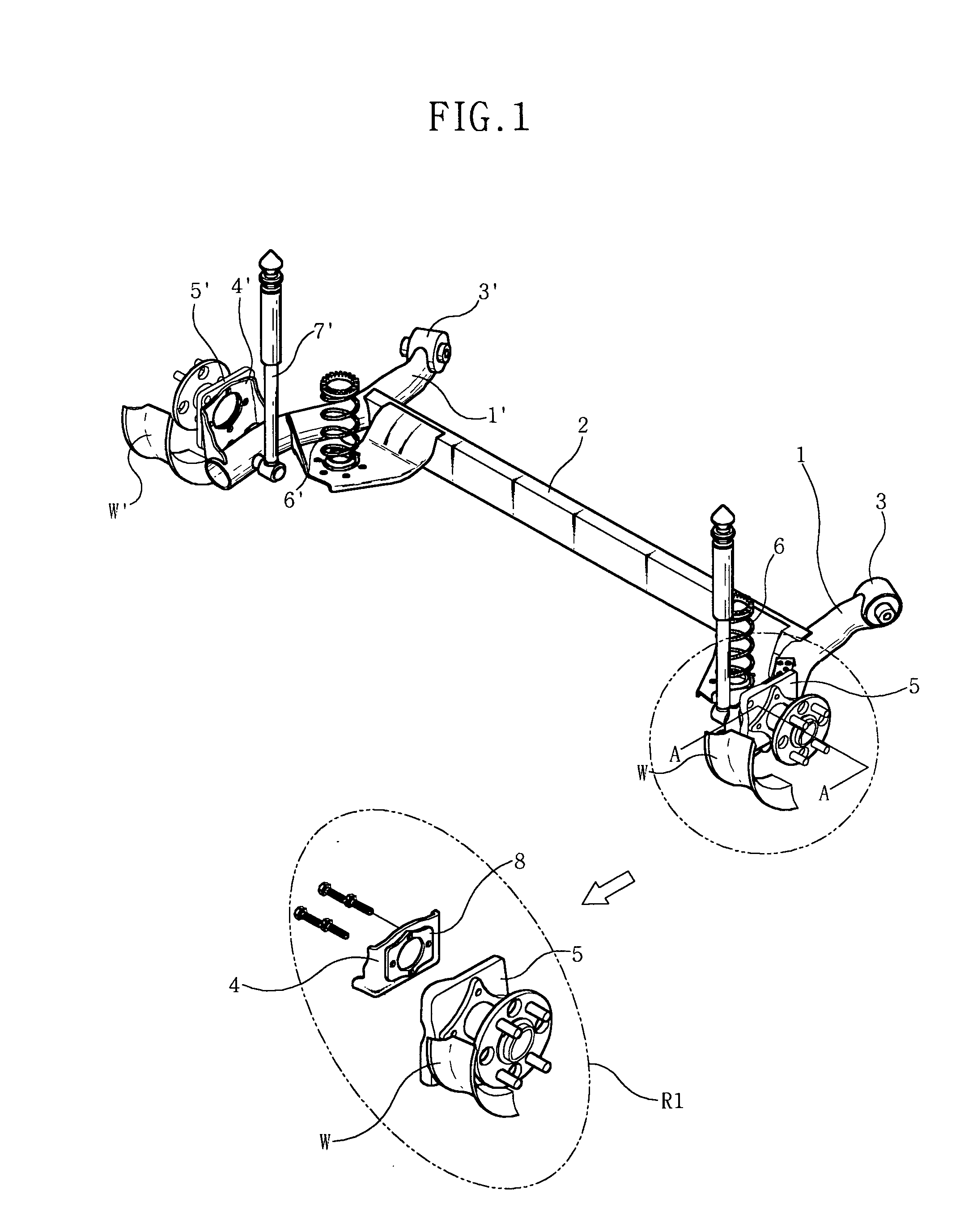
[0029] As shown in FIGS. 3 through 6, in the torsion beam suspension system having the wheel angle adjustment apparatus of the present invention, two trailing arms 10 and 10′ are coupled to each other by a torsion beam 20. Two joints 30 and 30′, each having a bushing, are provided on front ends of the...


PUM


Abstract

Disclosed herein is a wheel angle adjustment apparatus for automobile suspension systems. The wheel angle adjustment apparatus of the present invention has a structure such that upper, lower, left and right gaps between a spindle bracket and a wheel bracket are changed by tightening or loosening a plurality of locking bolts that couples the spindle bracket and the wheel bracket together. Therefore, toe and camber angles of each wheel are easily adjusted by tightening or loosening the locking bolts. In particular, when the present invention is used in a suspension system such as a torsion beam suspension system which has a structure such that a wheel alignment using a connection part provided between the automobile body and wheels is impossible, the wheels are easily aligned merely by adjusting the gap between the spindle bracket and the wheel bracket.

Description

BACKGROUND OF THE INVENTION [0001] 1. Field of the Invention [0002] The present invention relates generally to a wheel angle adjustment apparatus for an automobile suspension system and, more particularly, to a wheel angle adjustment apparatus for an automobile suspension system, which has a structure that allows toe and camber angles of wheels to be easily adjusted. [0003] 2. Description of the Related Art [0004] As well known to those skilled in the art, a suspension system for an automobile is a device that couple wheels to an automobile body. A suspension system absorbs impact and vibration transferred from a road surface while the automobile is in motion, thus enhancing the riding comfort and stability of the automobile. [0005] Such a suspension system is classified into a single body type suspension system, in which left and right wheels are integrally coupled to each other through an automobile axle, and an independent type suspension system, in which left and right wheels ar...

Claims


Application Information

Patent Timeline
IPC IPC(8): B62D17/00
CPCB60G7/008B60G21/051B60G2200/46B60G2200/4622B60G2202/12B60G2202/136B60G2204/124B60G2204/148B60G2204/416B60G2204/43B60G2204/4402B60G2204/61B60G2206/20B60G2206/50B60G3/00B62D17/00
Inventor NAM, DUK-WOO
Owner DONG HEE IND
Why Eureka
Try Eureka