Check patentability & draft patents in minutes with Patsnap Eureka AI!

Method of reduction processing of steel-making slag

a technology of steel-making slag and processing method, which is applied in the direction of lighting and heating apparatus, charge manipulation, furniture, etc., can solve the problems of large amount of steel-making slag generated, expansion and collapse, and restrict the use of steel-making slag, etc., and achieve the effect of low cos

Active Publication Date: 2015-05-21
NIPPON STEEL CORP
View PDF4 Cites 3 Cited by
  • Summary
  • Abstract
  • Description
  • Claims
  • Application Information

AI Technical Summary

Benefits of technology

[0020]According to the aspect described above, it is possible to modify, at low cost, the steel-making slag into a material that can be used for various applications such as a cement raw material, a civil engineering material, and a ceramic products, and recover the valuable elements such as Fe, Mn, and P into the molten iron by reduction. Further, it is possible to recycle Fe and Mn into the steel-making processes, and use P as a phosphate fertilizer or phosphoric acid material.

Problems solved by technology

During the steel making processes, a large amount of steel-making slag is generated.
Although the steel-making slag contains, for example, P and metal components such as Fe and Mn, it also contains a large amount of CaO, which leads to expansion and collapse.
This has restricted the steel-making slag to be used as, for example, a material for roadbed or aggregate.
However, this processing method requires batch processing to be continuously applied several times until a slag with predetermined components can be obtained, and hence, results in poor working efficiency.
As a result, working efficiency deteriorates.
Thus, it is assumed that the thermal efficiency deteriorates, and the amount of dust generated increases.
However, in the reduction tests described in Non-Patent Document 1, processing is performed to the cold steel-making slag, which has been solidified and crushed, and hence, the energy-consumption rate is large.
However, the method described in Patent Document 3 also involves the cold slag as the target of the processing, and hence, the energy-consumption rate is large.
As described above, these methods of recovering valuable components from the slags each have a problem of poor working efficiency or large energy-consumption rate.

Method used


Image

  • Method of reduction processing of steel-making slag
  • Method of reduction processing of steel-making slag
  • Method of reduction processing of steel-making slag

Examples


example 1

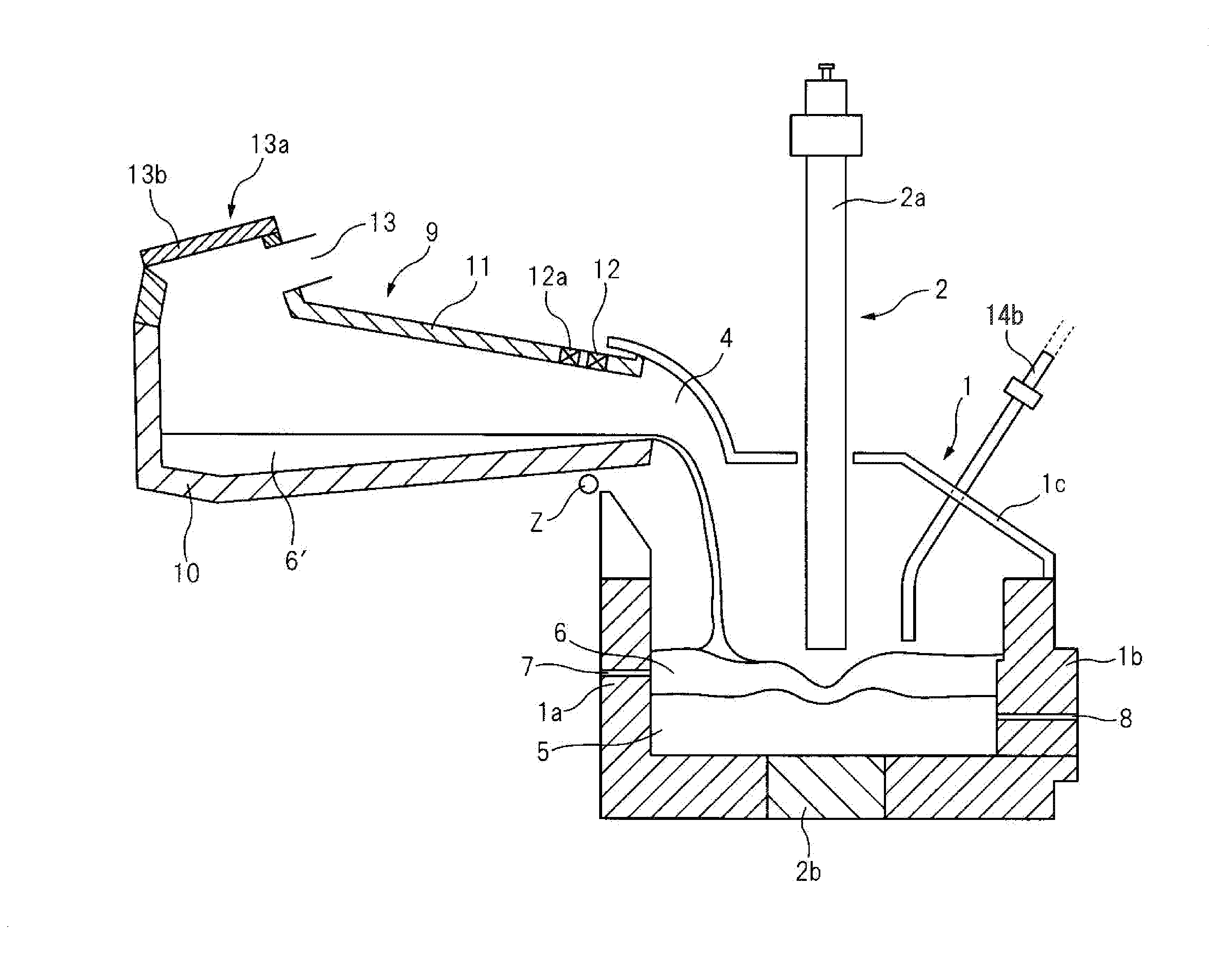
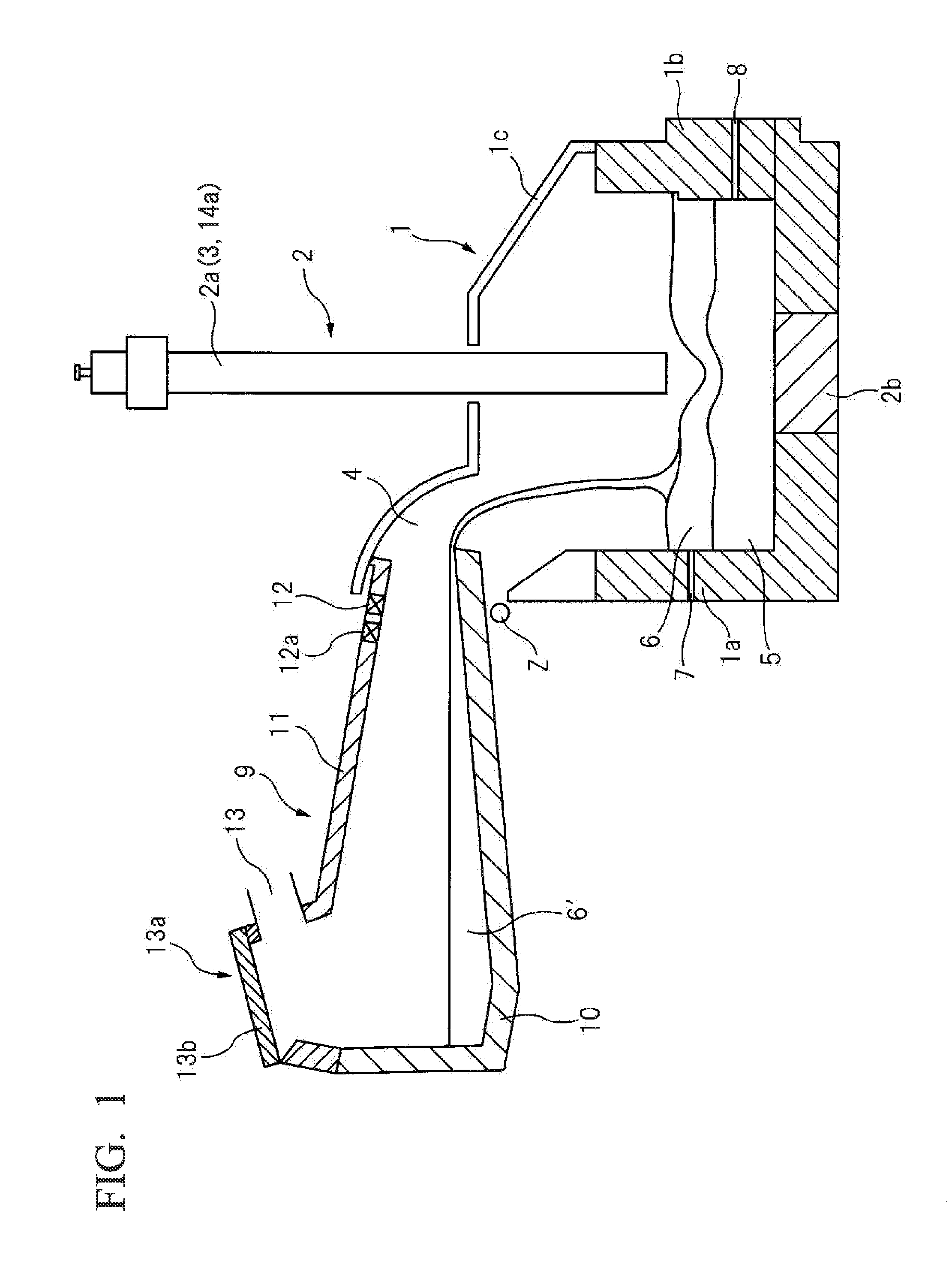
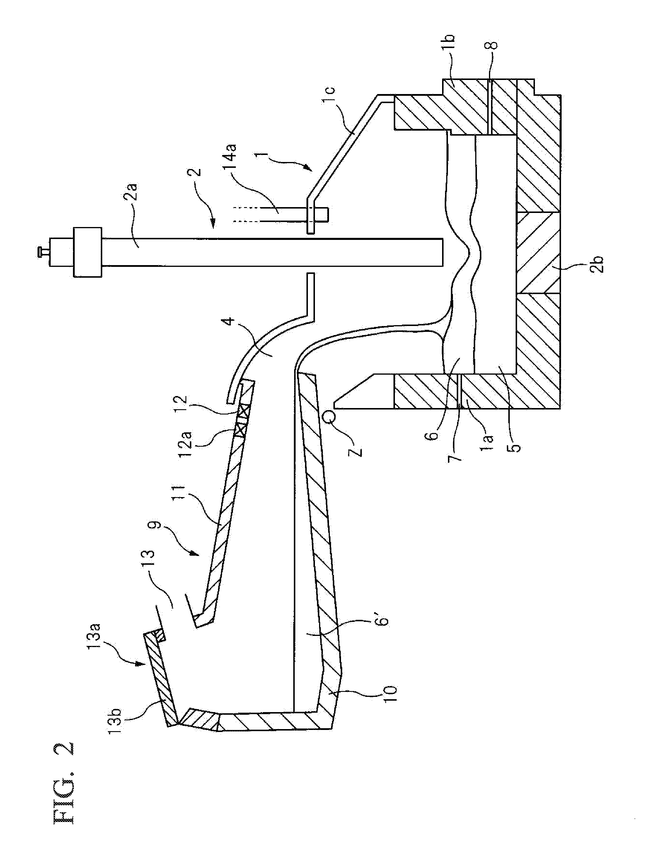
[0103]In a device illustrated in FIG. 2, the hot steel-making slag 6′ discharged from a converter in a high-temperature molten state (rate of solid phase: not more than 30%) was charged into the slag supplying container 9, and was temporarily contained and maintained. Then, the slag supplying container 9 was tilted once every 10 minutes to intermittently charge the hot steel-making slag 6′ with approximately 8 tons for each charge into the direct-current electric furnace 1.

[0104]The hot steel-making slag 6′ was charged into the electric furnace 1 under conditions where pig iron with approximately 130 tons was contained in the electric furnace 1 and a molten slag layer subjected to reduction processing existed on the pig iron with a thickness of approximately 200 mm. Note that the reason for setting the amount of inflow of the hot steel-making slag 6′ to approximately 8 tons for each charge is that it has been checked, through preliminary experiments using an actual device, that stro...

example 2

[0112]The molten slag 6 was subjected to a reduction and modification process under the same conditions as those for Example 1 except that the hollow electrode 3 was used for the electrode 2, and, in place of the auxiliary-raw-material supplying tube 14a, the hollow portion of the hollow electrode 3 was used as the auxiliary-raw-material supplying tube 14a for supplying the slag modifying agent and the reducing agent.

[0113]Temperatures in the electric furnace 1 were controlled so as to be molten iron temperatures: 1450±5° C., and slag temperatures: 1550±5° C. The reduction processing of the molten slag 6 was continuously performed without causing the overflow of the molten slag 6.

[0114]During the reduction processing, the molten slag 6 was discharged once every hour with the amount of approximately 46 tons from the cinder notch 7, and the molten iron 5 was discharged once every five hours with the amount of approximately 44 tons from the tap hole 8. The components of the discharged ...

example 3

[0115]Slag were subjected to reduction processing under the same conditions as those in Example 1 except that, in the electric furnace 1, pig iron (C, 4.1 mass %) having components shown in Table 7 and having the concentration of C higher than that of Examples 1 and 2 was used, the slag supplying container 9 was tilted once every five minutes, and the amount of inflow of the hot steel-making slag 6′ is set to be approximately 4 tons for each charge.

TABLE 7(mass %)[C][Si][Mn][P][S]TemperatureComposition of molten4.10.010.320.120.0241450° C.iron

[0116]It should be noted that the reason for setting the amount of inflow of the hot steel-making slag 6′ to approximately 4 tons for each charge is that it has been confirmed, through preliminary experiments using an actual device, that strong foaming does not occur under the condition of Example 3 in which the molten pig iron has a concentration of C higher than that of Examples 1 and 2. As a result, the reduction processing of the molten sla...


PUM

PropertyMeasurementUnit
temperaturesaaaaaaaaaa
temperatureaaaaaaaaaa

Abstract

The method of reduction processing of steel-making slag, includes: a hot steel-making slag inflow process of continuously or intermittently charging, from a slag supplying container, hot steel-making slag to a molten slag layer on a molten iron contained in an electric furnace while adjusting an amount of inflow with the slag supplying container; a reducing agent supplying process of supplying a reducing agent to the molten slag layer; an electrifying and heating process of heating the molten iron and the molten slag layer through application of electric power; and a reduction process of continuing reduction processing of the hot steel-making slag in a non-oxidizing atmosphere while intermittently discharging either one or both of the molten iron or molten slag of the molten slag layer.

Description

TECHNICAL FIELD[0001]The present invention relates to a method of reduction processing of a steel-making slag that applies reduction processing to slag (steel-making slag) generated during steel making, and recovers valuable components while modifying properties of the steel-making slag so as to conform to various applications.[0002]The present application claims priority based on Japanese Patent Application No. 2012-144473 filed in Japan on Jun. 27, 2012, Japanese Patent Application No. 2012-144557 filed in Japan on Jun. 27, 2012, and Japanese Patent Application No. 2012-235692 filed in Japan on Oct. 25, 2012, the disclosures of which are incorporated herein by reference in their entirety.BACKGROUND ART[0003]During the steel making processes, a large amount of steel-making slag is generated. Although the steel-making slag contains, for example, P and metal components such as Fe and Mn, it also contains a large amount of CaO, which leads to expansion and collapse. This has restricte...

Claims


Application Information

Patent Timeline
Patent Type & Authority Applications(United States)
IPC IPC(8): C21C7/00C21C5/52
CPCC21C5/527C21C7/0087C21C2005/5235C21C2300/04F27B3/183F27B19/04F27D3/14C21C5/5229Y02P10/20F27D15/00C04B5/06
Inventor HARADA, TOSHIYAARAI, TAKASHIHIRATA, HIROSHI
Owner NIPPON STEEL CORP
Features
  • R&D
  • Intellectual Property
  • Life Sciences
  • Materials
  • Tech Scout
  • Unparalleled Data Quality
  • Higher Quality Content
  • 60% Fewer Hallucinations
Learn More