Recording apparatus

a recording apparatus and a technology for recording, applied in the direction of typewriters, printing, thin material processing, etc., can solve the problems of not being able to handle, not being able to adjust the depth direction of the entire recording apparatus, and being difficult to handl

Active Publication Date: 2015-06-11
SEIKO EPSON CORP
View PDF4 Cites 0 Cited by
  • Summary
  • Abstract
  • Description
  • Claims
  • Application Information

AI Technical Summary

Benefits of technology

[0009]An advantage of some aspects of the invention is to provide a recording apparatus in which paths for printing on both faces and a manual feeding path are included, manual feeding is easily performed, and an installation space is made small.

Problems solved by technology

For this reason, there is a problem in that a space is necessary on the rear surface side of the apparatus, it is not easy to handle, and a dimension in the depth direction of the entire apparatus becomes large.
Accordingly, similarly to the image forming apparatus which is described in JP-A-2006-160507, a space for manual feeding is necessary on the rear surface side of the apparatus, and it is not easy to handle.
When the medium accommodating unit is inserted into the mounting region in a state in which the path forming member comes down to the mounting region, there is a concern that the path forming member, or a mounting structure unit of the path forming member may be damaged.

Method used


Image

  • Recording apparatus
  • Recording apparatus
  • Recording apparatus

Examples


example

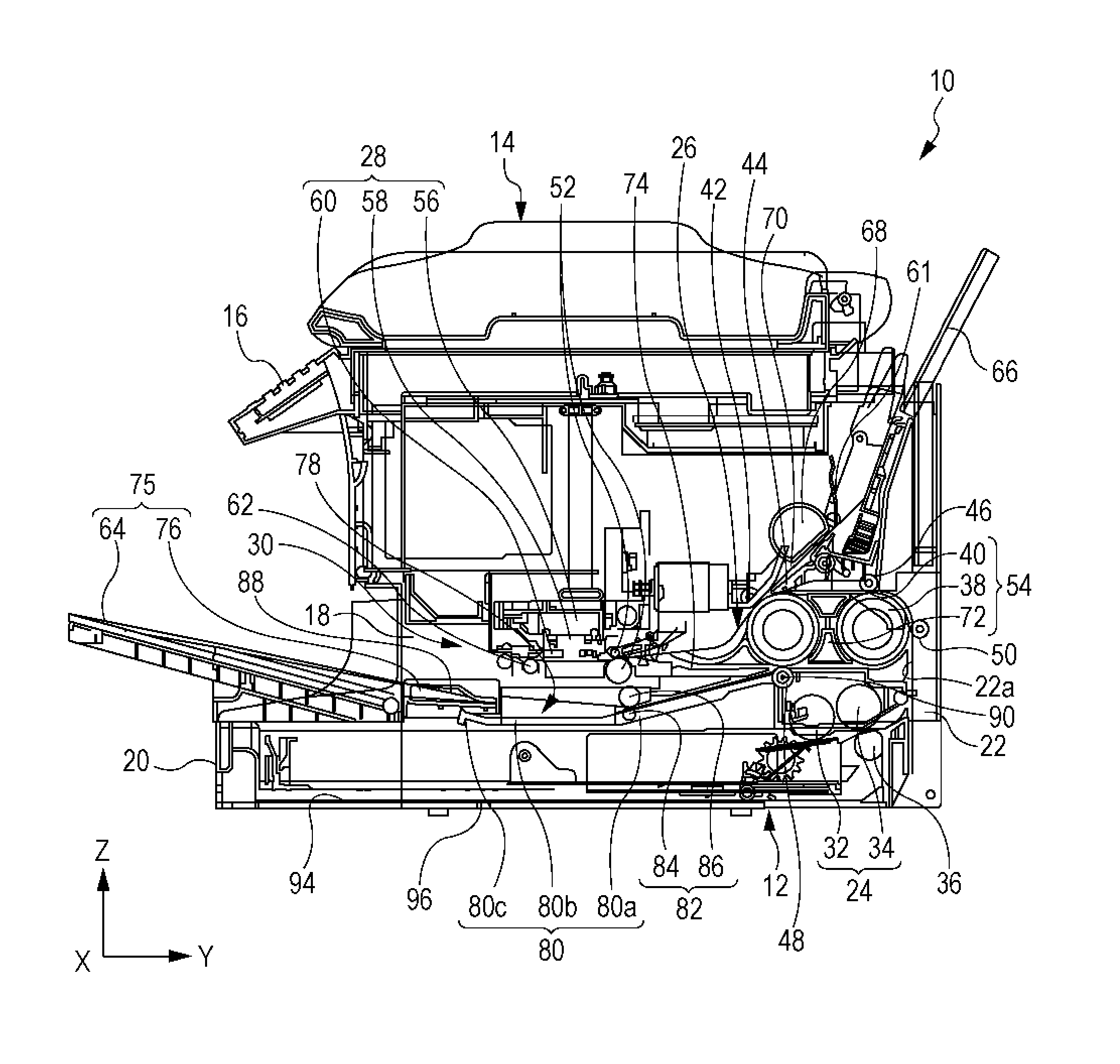
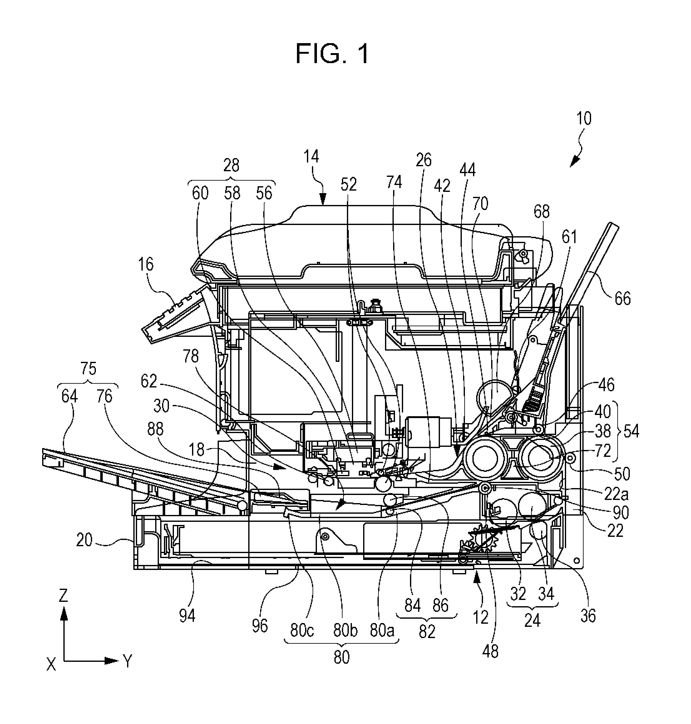
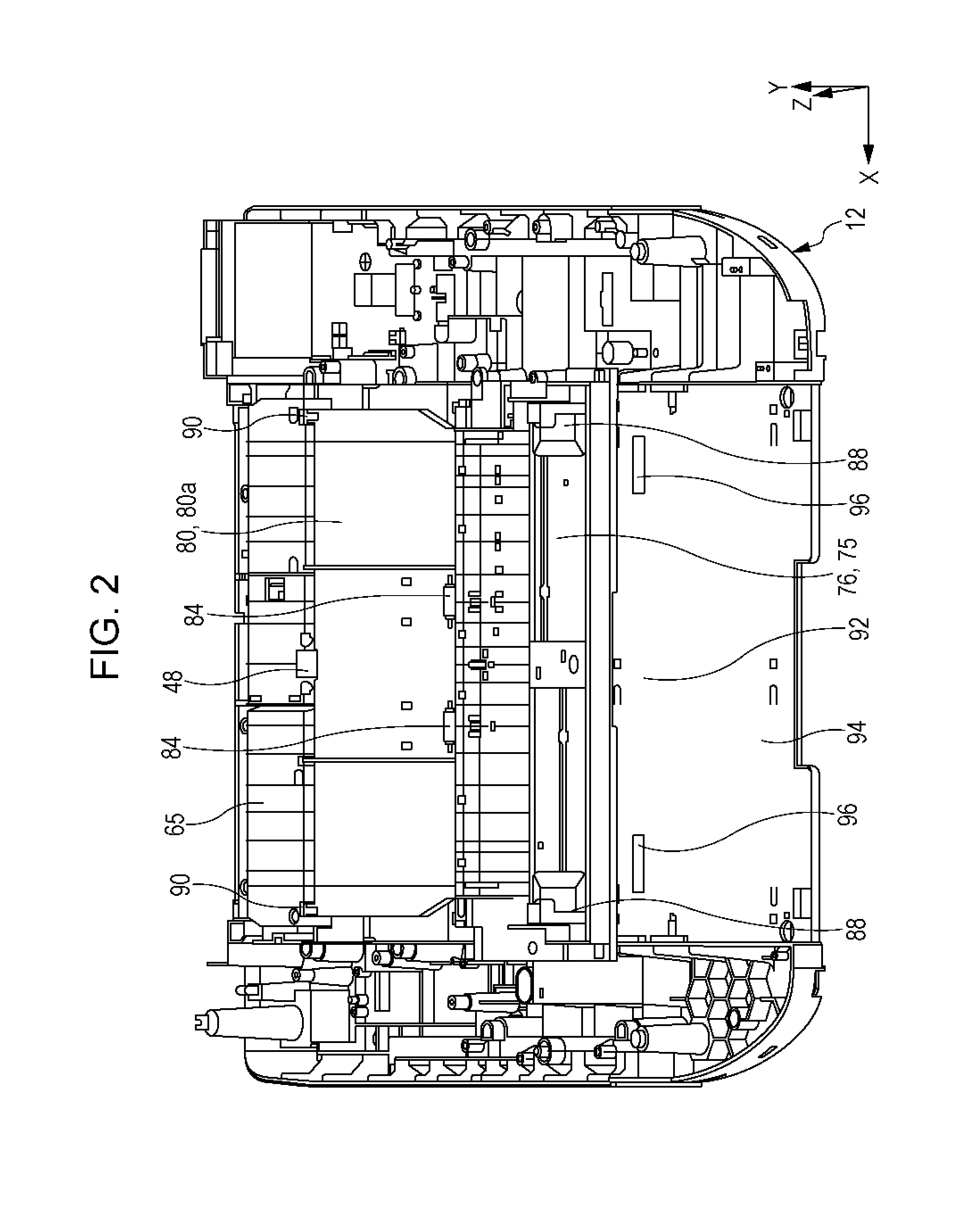
[0071]Subsequently, the first medium support unit 75 which also functions as the medium reception unit 75 and a second medium transport path 78 will be described with reference to FIGS. 1 to 6. The first medium support unit 75 includes the first medium support tray 64 and a paper guiding unit 76. In the apparatus main body 12, the paper guiding unit 76 is provided so as to be located between the recording head 58 of the recording unit 28 and the medium accommodating unit 20 as illustrated in FIG. 1. The paper guiding unit 76 is configured so as to be inserted from the first surface side to the second surface side in the opening portion 18, that is, from the −Y direction side to the +Y direction side in the Y axis direction in FIG. 1, and guide the medium which is supported by the first medium support tray 64 to the downstream side of the transport path.

[0072]Here, since the medium accommodating unit 20 can handle the medium from the −Y direction side in FIG. 1 which is the medium di...

modification example of example

[0094](1) In the example, the first driven roller 42, the second driven roller 44, the third driven roller 46, the fourth driven roller 48, and the fifth driven roller 50 are provided on the apparatus main body 12 side, however, the rollers may have a configuration in which the rollers are provided in the reversing transport path unit 72 along with the first roller 38 and the second roller 40, and are detachable from the apparatus main body 12 as the reversing transport path 54.

[0095](2) In the example, the transport path on the second medium support tray side 70 joins the first medium transport path 61 between the first driven roller 42 and the second driven roller 44 which respectively come into contact with the second roller 40, however, the transport path may join the first medium transport path 61 at the position of the first roller 38. According to such a configuration, it is possible to suppress the cost increase of the apparatus by sharing the transport path in a configurati...


PUM


Abstract

A recording apparatus includes a recording head which performs recording on a medium. The recording apparatus includes a first roller that reverses a medium which is transported from the recording head side and a medium reception unit that is provided on the downstream side of the recording head on the medium transport path on which the medium is transported. The medium reception unit also functions as a first medium support unit that supports a medium that is inserted from a discharging direction side of the medium.

Description

CROSS-REFERENCE TO RELATED APPLICATIONS[0001]The present application is a Continuation of U.S. patent application Ser. No. 14 / 225,802 filed on Mar. 26, 2014, which claims priority to Japanese Patent Application No. 2013-072176, filed on Mar. 29, 2013, which applications are hereby incorporated by reference in their entirety.BACKGROUND[0002]1. Technical Field[0003]The present invention relates to a recording apparatus which is represented by a fax machine, a printer, or the like.[0004]2. Related Art[0005]In recording apparatuses which are represented by a fax machine, a printer, or the like, there is an apparatus which can execute recording on both surfaces of a printing sheet as an example of a medium. Such a recording apparatus has a reversing path on which a recording sheet is reversed, and the recording sheet on which recording is performed is reversed on the reversing path, and is transported to a region facing a recording head again by having the rear surface as the front surfa...

Claims


Application Information

Patent Timeline
Patent Type & Authority Applications(United States)
IPC IPC(8): B41J13/02
CPCB41J13/02B65H5/06B65H2404/14B41J3/60B41J13/103B41J11/007
Inventor NAKATA, MASANORI
Owner SEIKO EPSON CORP
Why Eureka
Try Eureka