Motor vehicle drive assembly

a technology for motor vehicles and drive components, applied in mechanical equipment, wing accessories, lock applications, etc., can solve the problems of shortening the service life of motor vehicles, and achieve the effects of increasing the control range of output elements, reducing the number of motor vehicles, and increasing the service li

Active Publication Date: 2022-10-11
KIEKERT AG
View PDF17 Cites 0 Cited by
  • Summary
  • Abstract
  • Description
  • Claims
  • Application Information

AI Technical Summary

Benefits of technology

[0016]Either way, a particularly permanent and functionally reliable operation of the motor vehicle drive assembly according to the invention is first made available. This is because the use of the spiral spring, which acts as it were bidirectional for returning, means that the spiral spring in question can be used to realize higher spring torques and thus return torques for the output element compared to a leg spring. In other words, such spiral springs can basically be equipped with larger spring constants than leg springs in the context described. In addition, spiral springs generally allow a much larger control range of the output element and the associated contour than is observed with leg springs. As a result of this, a significantly higher strength and thus also an increased service life is observed for spiral springs compared to leg springs or also helical coil springs. This is especially true in the event that relatively high return torques are required on the output element. In addition, there is space to accommodate the spiral spring together with the contour and the lever connected to the inner spring leg of the spiral spring on the back of the output element and, in this way, only a small amount of installation space is required. In other words, a particularly compact embodiment is provided.

Problems solved by technology

In a long-term operation, such leg springs often have a high impact, which can shorten their service life.

Method used


Image

  • Motor vehicle drive assembly
  • Motor vehicle drive assembly

Examples


Embodiment Construction

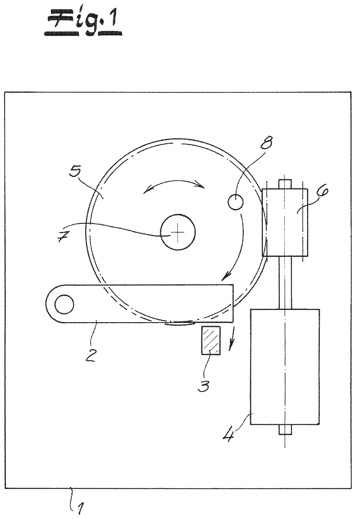
[0021]A motor vehicle drive assembly is shown in the figures. In the present case, the motor vehicle drive assembly is installed in a housing 1 of a motor vehicle door latch. This is of course only an example and is in no way restrictive.

[0022]The motor vehicle door latch having the housing 1 indicated in FIG. 1 has conventional components in its interior such as a release lever 2 and a pawl 3 as part of a locking mechanism (not shown in detail). The motor vehicle drive assembly has an electric motor 4 as well as an output element 5 driven indirectly or directly with the aid of the electric motor 4.

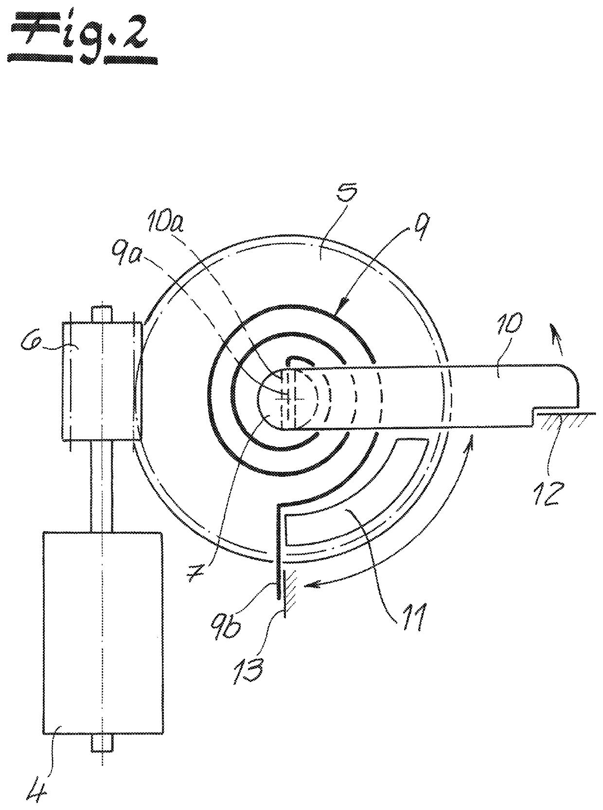
[0023]In the exemplary embodiment, the electric motor 4 provides a direct drive for the output element 5. For this purpose, the electric motor 4 has on the output side an output worm 6 on its output shaft, which meshes with a toothing (not shown in detail), on the output element 5 designed as a worm wheel 5. In this way, the worm wheel 5 can perform clockwise and counterclockwise rotation...


PUM


Abstract

A motor vehicle drive assembly, which is equipped with an electric motor and an output element, which is driven by the electric motor indirectly or directly. Furthermore, a spring associated with the output element is realized, which spring is designed to bidirectionally return the output element. According to the invention, the spring is designed as a spiral spring which is designed to be windable and unwindable proceeding both from the inner spring let and from the outer leg.

Description

FIELD OF INVENTION[0001]The invention relates to a motor vehicle drive assembly, which is equipped with an electric motor and at least one output element, which is indirectly or directly driven by the electric motor, and a spring associated with the output element, which spring is designed to bidirectionally return the output element.BACKGROUND OF INVENTION[0002]Motor vehicle drive assemblies are widely used in motor vehicles. Examples of this are mirror adjustments, seat adjustments, window regulators, but also unlocking devices on engine hoods, tailgates, and the like. Furthermore, such motor vehicle drive assemblies are increasingly used in connection with the locking and unlocking of charging plugs in associated receptacles in electric vehicles. In the scope of the present application, motor vehicle drive assemblies are very particularly preferred which are used in connection with motor vehicle doors and here in particular in connection with motor vehicle door latches.[0003]Such...

Claims


Application Information

Patent Timeline
Patent Type & Authority Patents(United States)
IPC IPC(8): E05B81/50E05B81/06E05B81/14E05B81/34E05B15/04
CPCE05B81/50E05B81/06E05B81/14E05B81/34E05B2015/042E05Y2201/434E05Y2201/482E05Y2201/702E05Y2201/704E05Y2900/531Y10T292/1082E05B2015/0496E05B2015/0486
Inventor INAN, ÖMERSCHOLZ, MICHAELSCHIFFER, HOLGERSZEGENY, PETER
Owner KIEKERT AG
Why Eureka
Try Eureka