Valve, in particular pilot-operated proportional directional poppet valve

Active Publication Date: 2017-10-03
HYDAC FLUITECHNIK GMBH
View PDF11 Cites 0 Cited by
  • Summary
  • Abstract
  • Description
  • Claims
  • Application Information

AI Technical Summary

Benefits of technology

[0017]Particularly advantageously, the control element is designed as a collar on the pilot valve closing member. The collar has at least one pressure-relief bore. A collar is a circumferential projection or flange on the pilot valve closing member. This configuration has the advantage that the pilot valve closing member is additionally centered relative to the main piston, and the projection on the pilot valve closing member is always oriented toward the supply aperture. A plurality of pressure-relief bores, which are disposed so as to be distributed over the circumference, can also be provided.
[0018]In a particularly advantageous embodiment, the supply aperture comprises a plurality of aperture bores. The opening cross-section of at least one aperture bore can be reduced by the control element. By splitting the supply aperture into a plurality of aperture bores, the supply aperture can be very easily controlled in a plurality of opening stages. In addition, the aperture bores preferably have the same diameter. The aperture bores can also have different diameters to additionally adapt the control behavior of the valve to the different prevailing load pressures and to provide the adjustment with a characteristic that deviates from linearity.
[0019]The aperture bores are conveniently disposed in the main piston so as to be offset relative to one another axially and/or over the circumference. This arrangement of the aperture bores also simplifies the reduction of the opening cross section by the pilot valve closing member. By the axial displacement of the pilot valve closing member relative to the main piston, one or more aperture bores that are located

Problems solved by technology

By preventing leakage in the hydraulic circuit, the load fork cannot lower on its own with or without a load, which would pose a safety problem.
The known control devices associated therewith have the disadvantage that, when the load forks are lowered without a load, only the dead weight of the moving parts, in particular in the form of the load forks, is available at the lift mast for pumping the hydraulic fluid from the working cylinder (plunger cylinder) back to the tank as a component of the hydraulic circuit.
In this connection, the known constant volumetric flow controller poses a particularly difficult obstacle to overcome, because the supply aperture thereof must be selected such that it is small enough that a control pressure differential of at least 7 bar can be established.
Lesser control pressures wou

Method used


Image

  • Valve, in particular pilot-operated proportional directional poppet valve
  • Valve, in particular pilot-operated proportional directional poppet valve
  • Valve, in particular pilot-operated proportional directional poppet valve

Examples


Example

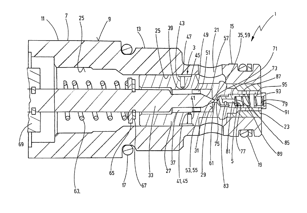
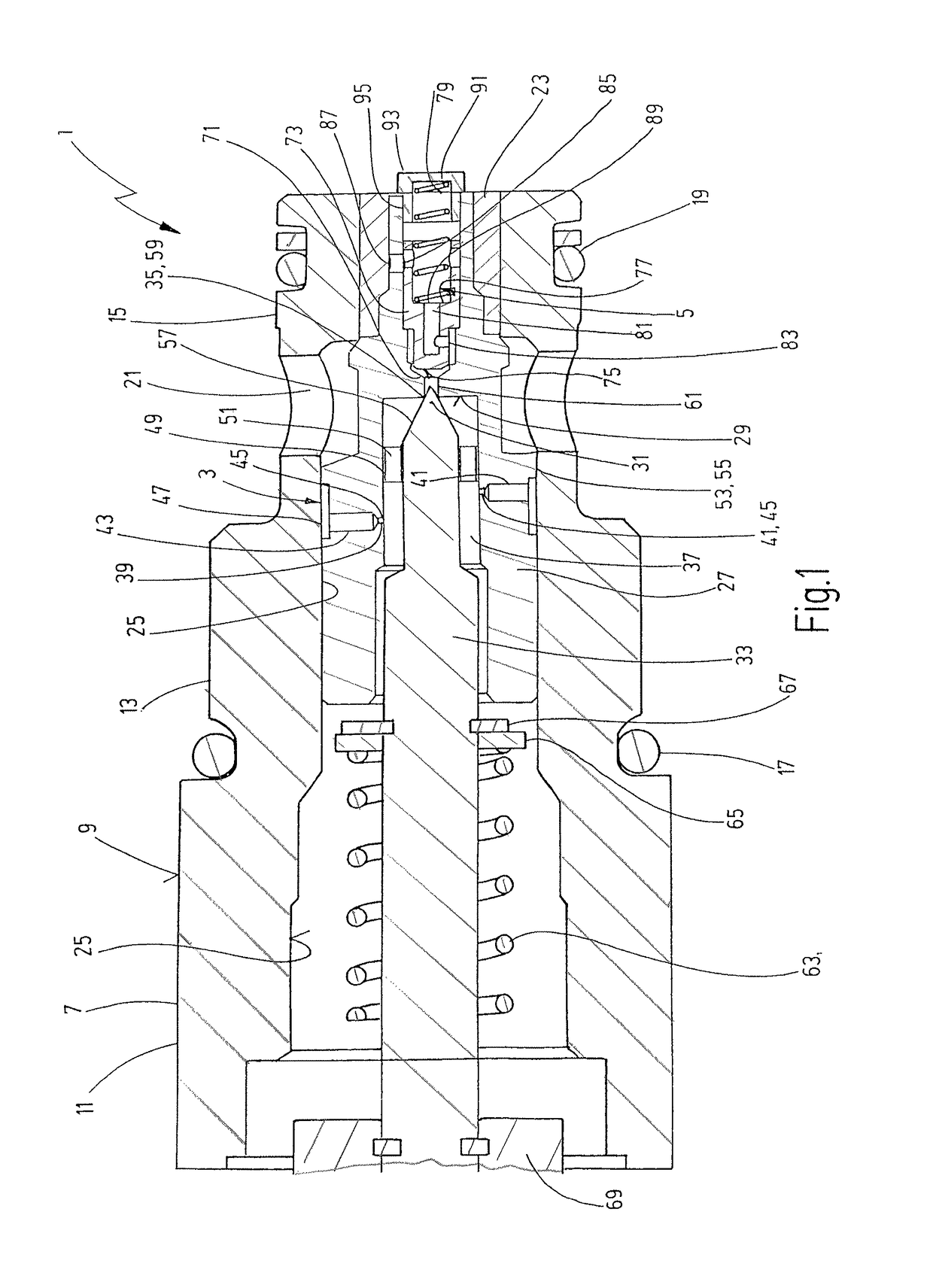
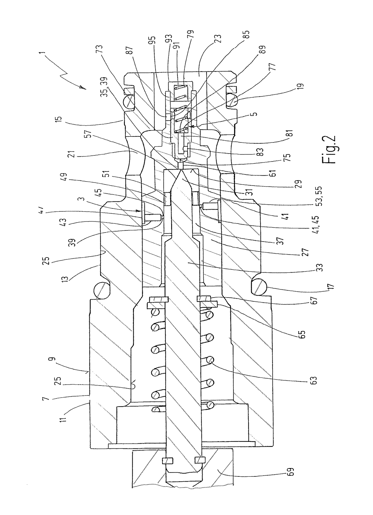
[0027]In FIGS. 1 to 3, the valve 1 is designed as a pilot-operated proportional directional valve having a cartridge design. The design is based on a conventional proportional directional poppet valve, into which a reducible supply aperture 3 and a maximum volumetric flow controller 5 have been integrated.

[0028]The valve 1 can be inserted into a valve block, which is not depicted in greater detail. To this end, the valve housing 7 is designed to taper in steps on the circumferential side 9. The individual steps are designed as a hexagonal step 11, a threaded step 13, and a simple step 15, and are sealed by circumferential annular seals 17, 19. The valve housing 7 comprises a lateral fluid inlet 21 and a fluid outlet 23 at the base. A main piston 27 is inserted into an axial bore 25 of the valve housing 7. The fluid stream between the fluid inlet 21 and the fluid outlet 23 can be regulated by the main piston 27.

[0029]A pilot valve 31 is provided on a rear face 29 of the main piston 2...


PUM


Abstract

A valve, in particular a pilot-operated proportional directional poppet valve, has a valve housing (7) with a fluid inlet (21) and a fluid outlet (23). The fluid stream between the fluid inlet (21) and the fluid outlet (23) is adjustable by a main piston (27). A pilot valve chamber (37) provided on a rear face (29) of the main piston (27) has a pilot valve closing member (33) movable by an actuating device (69). By closing member (33) the fluid stream between the pilot valve chamber (37) and the fluid outlet (23) can be adjusted. An inlet aperture (3) is arranged between the fluid inlet (21) and the pilot valve chamber (37). A maximum volumetric flow controller (5) is in the main piston (27) in an outflow between the pilot valve chamber (37) and the fluid outlet (23).

Description

FIELD OF THE INVENTION[0001]The invention relates to a valve, in particular a pilot-operated proportional directional poppet valve, having a valve housing with a fluid inlet and a fluid outlet. A fluid stream between the fluid inlet and the fluid outlet is adjustable by a main piston. A pilot valve chamber provided on a rear face of the main piston has a pilot valve closing member movable by an actuating device such that the fluid stream between the pilot valve chamber and the fluid outlet can be adjusted. A supply aperture is disposed between the fluid inlet and the pilot valve chamber.BACKGROUND OF THE INVENTION[0002]In the case of fork-lift trucks, loads of load forks are often lowered in a proportional manner by poppet valves having a constant opening behavior. The poppet valves in this case can be directly actuated or can be pilot-operated. The use of poppet valves is necessary, in particular, because fork-lift truck manufacturers require a “stacker-tight” load behavior that al...

Claims


Application Information

Patent Timeline
IPC IPC(8): F16K31/00F16K1/52F16K31/40F15B13/01
CPCF16K1/526F15B13/015F16K31/408Y10T137/7771
Inventor BRUCK, PETERBILL, MARKUS
Owner HYDAC FLUITECHNIK GMBH
Why Eureka
Try Eureka