Laminar structure and a production method for same
Active Publication Date: 2014-05-01
KOREA INST OF IND TECH
View PDF2 Cites 14 Cited by
Summary
Abstract
Description
Claims
Application Information
AI Technical Summary
This helps you quickly interpret patents by identifying the three key elements:
Problems solved by technology
Method used
Benefits of technology
Benefits of technology
The patent describes a method for creating a three-dimensional structure using electrospraying and inkjet printing processes. This can be used to create a laminar structure for fuel cells, which offers economic and durability advantages. The method also allows for easier content control of catalysts, such as platinum, and increases catalyst stability. Additionally, the use of roll-to-roll mass production technology ensures uniformity of performance.
Problems solved by technology
Considering the fact that South Africa has 88% of the world's platinum elements containing Pt therein, there are always the problems such as uneven resources distribution and supply and demand instability.
Accordingly, the platinum (Pt) price is expected to continue to rise and the issue of PEMFC price can hardly be addressed sufficiently even when the costs of the other materials are greatly reduced.
Method used
Image
Click on the blue label to locate the original text in one second.
Reading with bidirectional positioning of images and text.
[0071]The electrosprayed layer formed by the electrospraying process explained above may also be used as a catalytic electrode layer. Accordingly, the technical aspects explained above regarding the electrosprayed layer are commonly applicable for the catalytic electrode layer too. The electrospraying ink for use in the electrospraying process may be a kind of ink which is formed from catalytic material and ionconductive polymer and solvent. Further, the catalytic material may include Pt catalyst.
[0072]FIG. 3 is a schematic, cross-section view provided to explain a state in which a catalytic electrode layer of the laminar structure is formed by electrospraying process, according to a variety of embodiments.
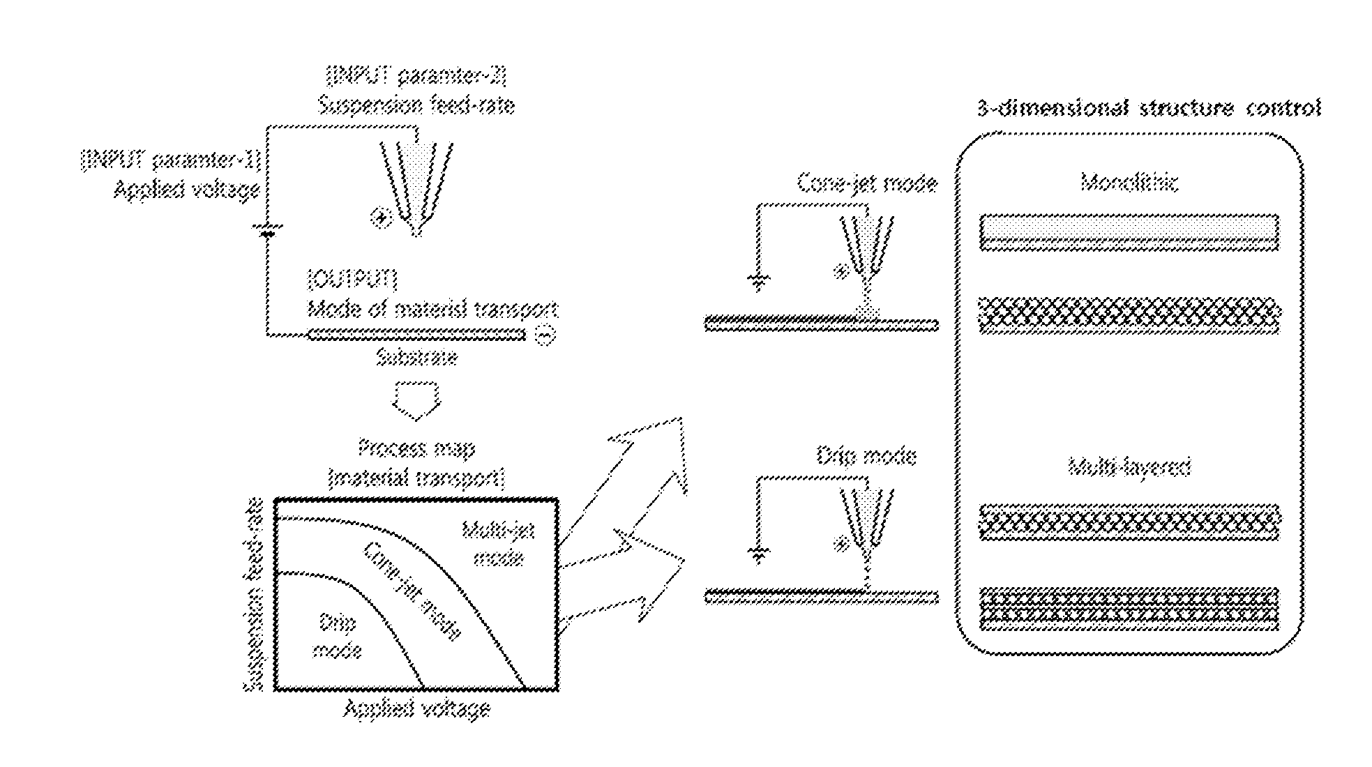
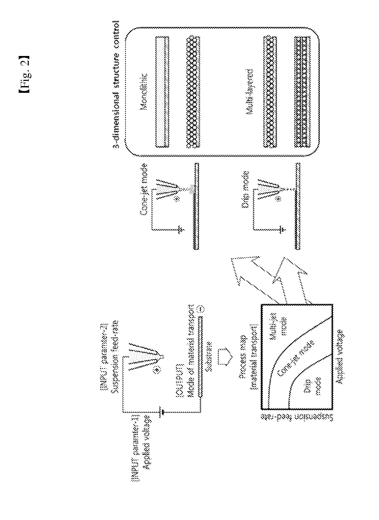
[0073]Referring to the cross-section view of FIG. 3 (left-hand side), the catalytic electrode layer may include monolithic electrode layer in which Pt catalyst is homogenously distributed by coating, or the like.
[0074]The ‘graded structure’ herein may ref...
second embodiment
Inkjet Layer
[0078]Next, the laminar structure (Hereinbelow ‘second laminar structure’) according to the second embodiment will be explained in detail. The second laminar structure may refer to the laminar structure incorporating therein an inkjet layer, in which the inkjet layer may be used for the micro-porous layer (MPL), or the catalytic electrode layer as in the case of the electrosprayed layer according to various embodiments. Throughout the description, the like or similar technical issues or constitution to those explained above will be briefly mentioned or not explained, but referred to the description provided above for the sake of brevity.
[0079]FIG. 4 is a conceptual view provided to explain an inkjet printing process, and FIG. 5 is a conceptual view provided to explain a catalytic electrode layer in which Pt catalyst is formed as a graded structure by inkjet printing process.
[0080]The second laminar structure may include an inkjet layer which is formed by the inkjet print...
[0090]The inkjet layer formed in the inkjet printing process explained above may be used for the micro-porous layer (MPL) formed on a surface of gas diffusion layer (GDL). Accordingly, the technical characteristics explained above regarding the inkjet layer can be commonly applied for the micro-porous layer too. The micro-porous layer may be formed as monolithic structure or porous graded structure, according to adjustment of the inkjet substance transport mode.
[0091]Although not illustrated in the drawings, the micro-porous layer may be formed as a monolithic structure. For example, when the inkjet substance transport mode is line mode deposition, the inkjet ink is continuously jetted out to form a line-type pattern of inkjet layer. As a result, the micro-porous layer of monolithic structure is formed. Further, when the inkjet substance transport mode is the dot mode deposition, the inkjet ink may be jetted out as the inkjet droplets to be laminated as dot-shaped ...
PUM
Abstract
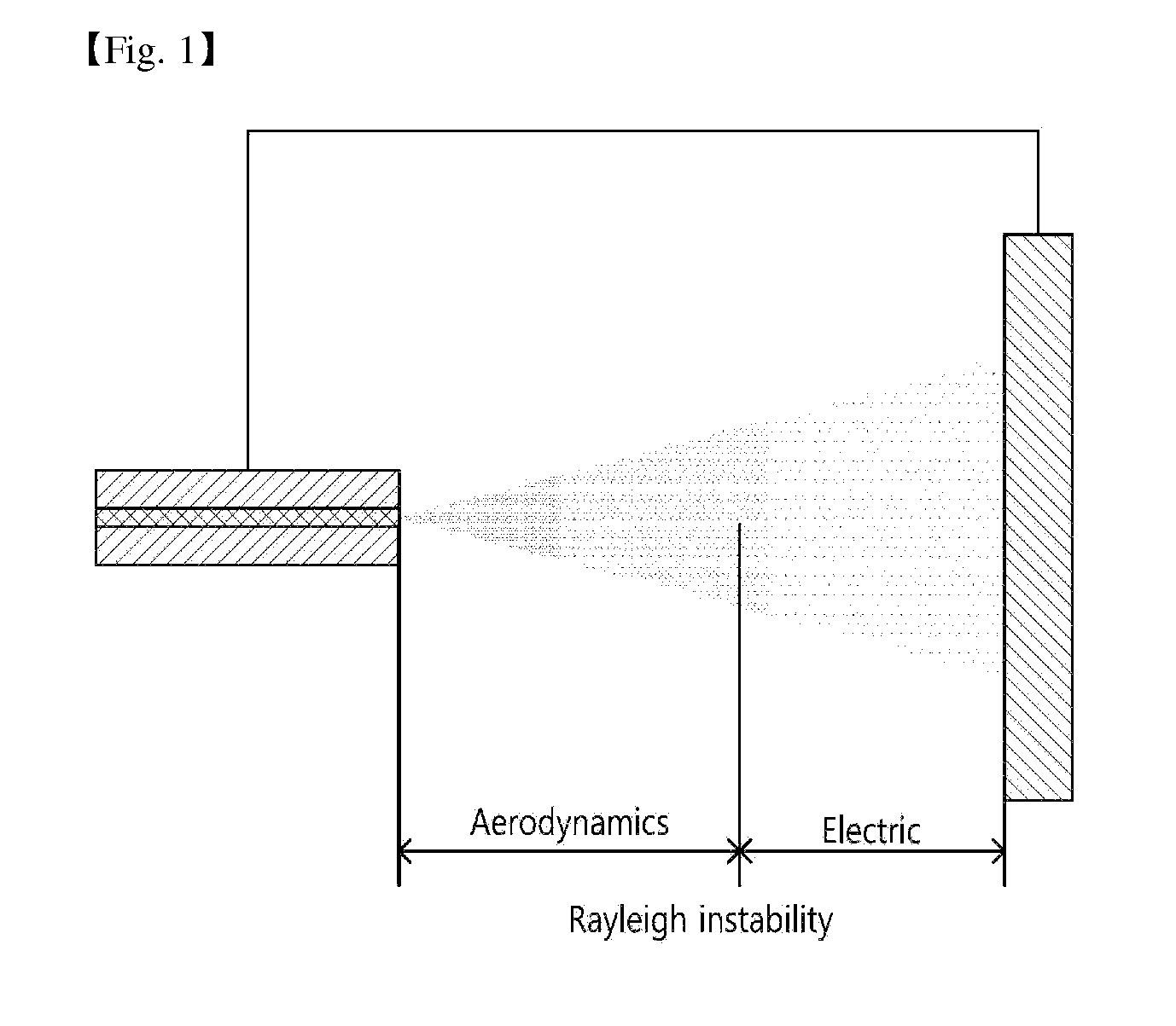
The present invention relates to a laminar structure which is used in a microporous layer, an electrode layer or the like of a membrane electrode assembly for a fuel cell, and also relates to a production method for same. The laminar structure is a laminar structure which is comprised in the membrane electrode assembly (MEA) of a polymerelectrolyte membrane fuel cell (PEMFC), and comprises an electrosprayed layer which is formed by the lamination of electrospraying ink, that has been charged by means of an electric field, through an electrospraying process in which the electrospraying ink is dispersed and sprayed as electrospraying liquid droplets, and, in the electrospraying process, the electrospraying substance transmission mode is set in accordance with the adjustment of electrospraying process variables. When the present invention is employed, an optimal substance transmission route is formed and three dimensional structure control is allowed through the electrospraying process and / or an inkjet printing process, and thus it is possible to simultaneously ensure economic advantages and durability when producing a laminated structure which is used in a microporous layer, an electrode layer, or the like of a membrane electrode assembly for a fuel cell.
Description
TECHNICAL FIELD[0001]The present invention relates to a laminar structure which is used in a micro-porous layer, or electrode layer for a membrane-electrode assembly for a fuel cell, and a production method thereof.BACKGROUND ART[0002]The high-carbon society that is heavily relying on fossil fuel-based growth will change to low-carbon society and then to hydrogen society where continuous growth is possible. For such a turn into hydrogen society, the polymerelectrolyte membrane fuel cell (PEMFC) has been categorized as the technology to utilize hydrogen and investigated for a considerable period of time on its potential for industrialization. The PEMFC has larger current density and power density compared to other forms of fuel cells, while it has relatively smaller volume and weight, thus is actively researched and developed for the purpose of commercialization in the field of transportation equipments worldwide.[0003]For the commercialization, above all, it is necessary to ensure ...
Claims
Application Information
Patent Timeline
Application Date:The date an application was filed.
Publication Date:The date a patent or application was officially published.
First Publication Date:The earliest publication date of a patent with the same application number.
Issue Date:Publication date of the patent grant document.
PCT Entry Date:The Entry date of PCT National Phase.
Estimated Expiry Date:The statutory expiry date of a patent right according to the Patent Law, and it is the longest term of protection that the patent right can achieve without the termination of the patent right due to other reasons(Term extension factor has been taken into account ).
Invalid Date:Actual expiry date is based on effective date or publication date of legal transaction data of invalid patent.

