
Medical system including vented tip protector

Inactive Publication Date: 2005-08-11
BAXTER INT INC +1
View PDF57 Cites 25 Cited by
  • Summary
  • Abstract
  • Description
  • Claims
  • Application Information

AI Technical Summary

Benefits of technology

[0041] With the above embodiments, one advantage of the present invention is to provide improved systems and methods for performing dialysis.
[0042] Another advantage of the present invention is to provide improved systems and methods for performing peritoneal dialysis.
[0043] A further advantage of the present invention is to provide an automated peritoneal dialysis system and method of operating same.
[0044] Still another advantage of the present invention is to provide an automated peritoneal dialysis system that provides dialysis therapy advantages.
[0045] Still a further advantage of the present invention is to provide an automated peritoneal dialysis system that has economic advantages.
[0046] Yet another advantage of the present invention is to provide an automated peritoneal dialysis system that has quality of life advantages.

Problems solved by technology

Due to disease, insult or other causes, a person's renal system can fail.
The balance of water, minerals and the excretion of daily metabolic load is no longer possible in renal failure.
During renal failure, toxic end products of nitrogen metabolism (urea, creatinine, uric acid, and others) can accumulate in blood and tissues.
Manual peritoneal dialysis performed by the patient requires a significant amount of time and effort from the patient.
This inconvenient procedure leaves ample room for improvement and therapy enhancements to improve patient quality of life.
One common problem with current home systems is that they are susceptible to electrical shock due to “leakage current”.
However, if the protective earth conductor becomes open circuited, the patient could be at risk of electrical shock.
Leakage currents are normally small, however, the amount of current required to produce adverse physiological effects in patients is also small.
Accordingly, leakage currents must be limited as much as possible by the design of the equipment and be within safety limits.

Method used


Image

  • Medical system including vented tip protector
  • Medical system including vented tip protector
  • Medical system including vented tip protector

Examples


Embodiment Construction

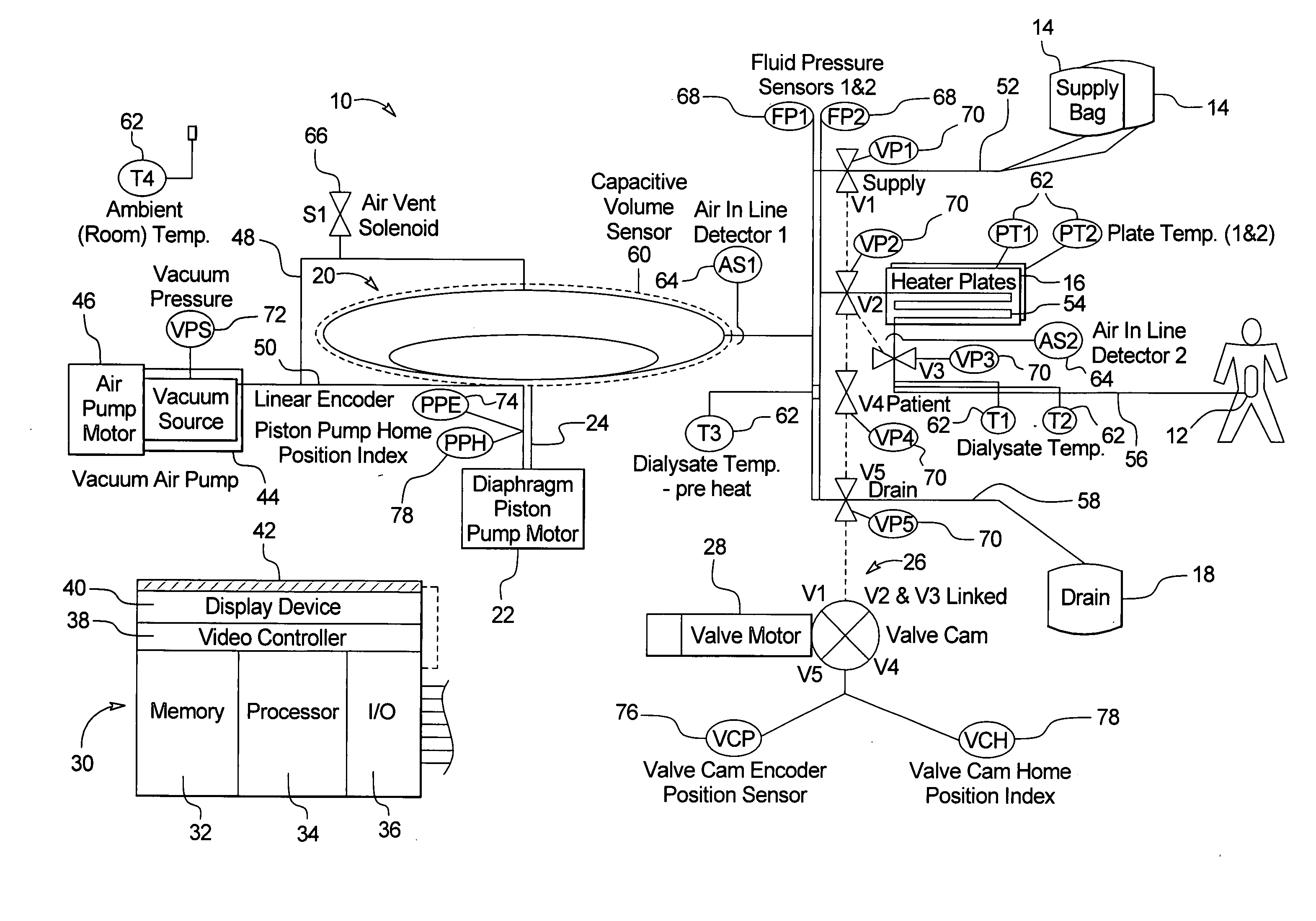
[0080] The present invention relates to dialysis systems and methods of performing dialysis. In particular, the present invention relates to a system and method for automatically providing peritoneal dialysis therapy to patients. The present invention provides automatic multiple exchanges of dialysis fluid to and from the patient's peritoneal cavity. The automatic exchanges of dialysate include drain, fill, and dwell periods, which usually occur while the patient sleeps. A typical therapy can include three to five exchanges of dialysis fluid. The present invention, in an embodiment, provides a single pass system, wherein the dialysate passes through the peritoneal cavity only once before being disposed. While the present invention performs peritoneal dialysis, it is also suitable for other types of dialysis and other medical fluid transfer operations.

I. The System Generally

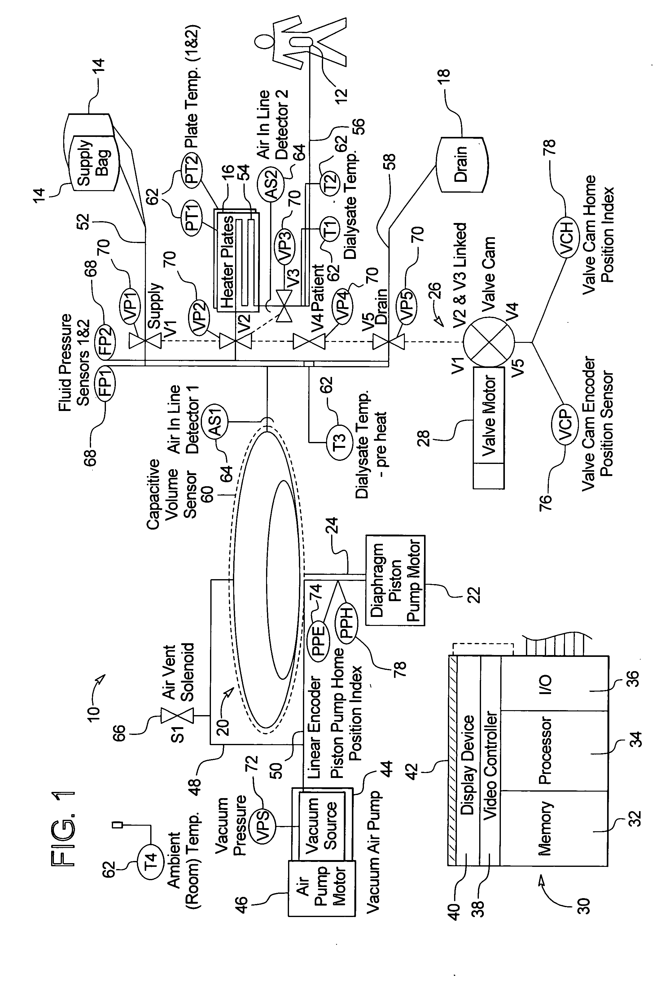
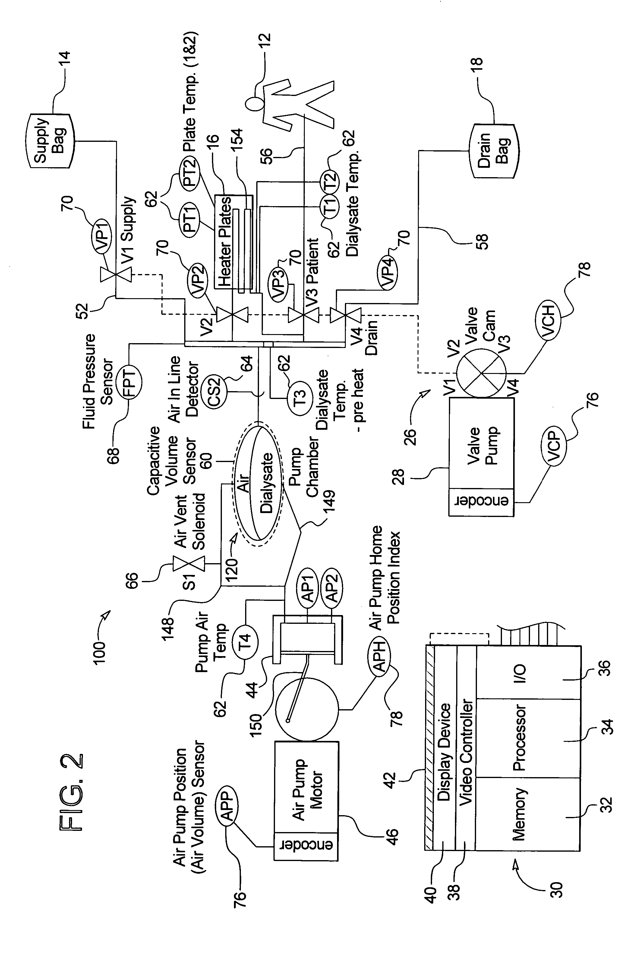
[0081] Referring now to the drawings and in particular to FIG. 1, a typical therapy performed by the system ...


PUM

PropertyMeasurementUnit
Pressureaaaaaaaaaa
Hydrophobicityaaaaaaaaaa

Abstract

A method, system and apparatus for performing peritoneal dialysis are provided. To this end, in part, a medical system is provided that includes (i) a liquid pump; (ii) tubing in communication with the liquid pump; and (iii) at least one processor that operates with the liquid pump to: (a) pump liquid through the tubing, the tubing having an end and a hydrophobic filter at the end, the filter allowing air but not the liquid to escape from the end of the tubing, (b) receive a signal indicating a pressure increase inside the tubing, and (c) cause the pumping to stop when air has been purged substantially from the tubing.

Description

PRIORITY CLAIM [0001] This application is a divisional application of U.S. patent application Ser. No. 10 / 155,579; Entitled: “VENTED MEDICAL FLUID TIP PROTECTOR”, filed May 24, 2002.BACKGROUND OF THE INVENTION [0002] The present invention generally relates to dialysis systems. More specifically, the present invention relates to automated peritoneal dialysis systems. The present invention also relates to methods of performing automated peritoneal dialysis and devices for performing same. [0003] Due to disease, insult or other causes, a person's renal system can fail. In renal failure of any cause, there are several physiological derangements. The balance of water, minerals and the excretion of daily metabolic load is no longer possible in renal failure. During renal failure, toxic end products of nitrogen metabolism (urea, creatinine, uric acid, and others) can accumulate in blood and tissues. [0004] Kidney failure and reduced kidney function have been treated with dialysis. Dialysis...

Claims


Application Information

Patent Timeline
IPC IPC(8): A61M1/28A61M39/10A61M39/20
CPCA61M1/28A61M39/10A61M39/20A61M2039/205A61M2205/12A61M1/288A61M2205/50A61M2205/581A61M2205/583A61M2205/7536A61M2205/3584A61M1/166A61M1/155A61M1/1565A61M1/159A61M1/153A61M1/1561
Inventor BOWMAN, JOSEPH H. JR.LUNDTVEIT, LOREN M.ALVARO, JOSEKELLAM, BENBUSBY, DONEU, BRUCE MING-DA
Owner BAXTER INT INC
Learn More