
Automatic continuous image engraving device

a continuous image and engraving technology, applied in the field of automatic continuous image engraving devices, can solve the problems of long transfer path in a plane and increase the size of the and achieve the effect of compact installation space of the devi

Active Publication Date: 2021-04-20
WORLD VENTURE CORP
View PDF23 Cites 0 Cited by
  • Summary
  • Abstract
  • Description
  • Claims
  • Application Information

AI Technical Summary

Benefits of technology

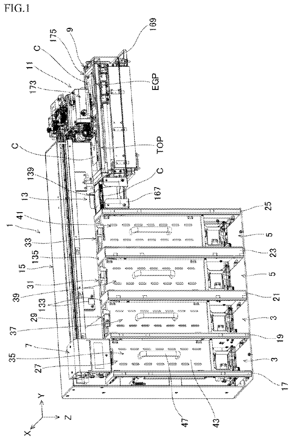
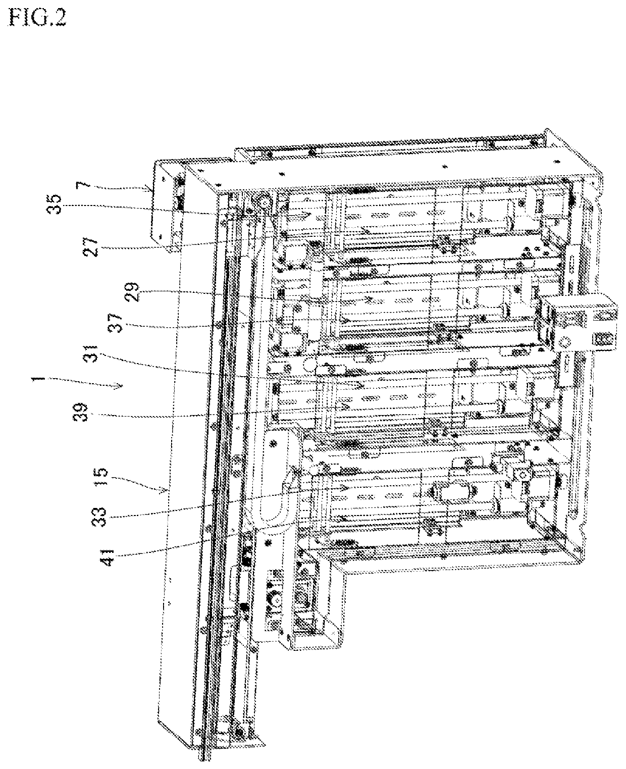
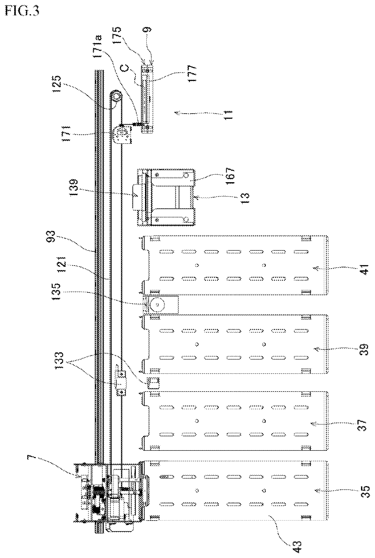
[0020]The present invention, because of the aforementioned configuration, can arrange the unengraved medium accommodating part and the engraved medium accommodating part and the medium positioning and conveying part and the image engraving part in line in the linear traveling direction of the medium dispenser, thereby making an installing space of the device compact.

Problems solved by technology

A problem to be solved is that a transfer path in a plane is long and increases in size of an installing space of a device.

Method used


Image

  • Automatic continuous image engraving device
  • Automatic continuous image engraving device
  • Automatic continuous image engraving device

Examples


Embodiment Construction

[0041]An object that is capable of decreasing in size of an installing space of a device is accomplished by comprising an unengraved medium accommodating part that accommodates unengraved card-shaped engraving media vertically stacked, an engraved medium accommodating part that is arranged adjacent to the unengraved medium accommodating part and accommodates engraved card-shaped engraving media, a medium dispenser that adsorbs a highest one of the stacked unengraved card-shaped engraving media from an upper part of the unengraved medium accommodating part, moves the highest one to an outside of a region above the unengraved medium accommodating part and linearly travels in an adjacent direction of the unengraved medium accommodating part and the engraved medium accommodating part, a medium positioning and conveying part arranged in a traveling direction of the medium dispenser and configured to succeed to the unengraved card-shaped engraving medium at a succeeding position, move the...


PUM


Abstract

Provided are an automatic continuous image engraving device capable of decreasing in size of an installing space of the device. The device comprises an unengraved medium accommodating part, an engraved medium accommodating part, a medium dispenser, a medium positioning and conveying part, and an image engraving part, wherein the medium dispenser releases the unengraved card-shaped engraving medium to cause the same to be succeeded at the succeeding position, the medium positioning and conveying part returns the engraved card-shaped engraving medium after image engraving from the engraving position to the succeeding position, and the medium dispenser adsorbs the engraved card-shaped engraving medium at the succeeding position, moves the same upward, travels above the engraved medium accommodating part, and releases the engraved card-shaped engraving medium to be accommodated.

Description

FIELD OF THE INVENTION[0001]The present invention relates to an automatic continuous image engraving device to perform image engravings on card-shaped engraving media.BACKGROUND OF THE INVENTION[0002]Conventionally, devices of engraving an image on a magnetic card or synthetic paper were proposed as Patent literatures 1-3. Each device has a single function to conduct an engraving only and cannot conduct automatic continuous image engravings.[0003]Contrary, the applicant proposed an automatic continuous image engraving device of Patent literature 4.[0004]The automatic continuous image engraving device performs image engravings on cards such as credit cards and is provided with a card magazine, a card dispenser, a read / write unit, a card positioning part, a card mounting table, a card conveying part, an image engraving part, a card accommodating magazine, and a card conveying robot.[0005]The card magazine is capable of accommodating a plurality of rectangular cards that allow read / wri...

Claims


Application Information

Patent Timeline
Patent Type & Authority Patents(United States)
IPC IPC(8): B44B3/00B42D25/48B42D25/44B42D25/333
CPCB42D25/48B42D25/44B44B3/00B44B3/009B42D25/333B42D25/324B44B3/065B44B3/02B42D25/23B42D25/43B44B3/007B44B3/06
Inventor HOSHIYAMA, YUICHI
Owner WORLD VENTURE CORP
Learn More