Stacked multilayer connector

a multi-layer connector and connector technology, applied in the direction of coupling device connection, printed circuit, two-part coupling device, etc., can solve the problems of poor contact between layers, and achieve the effect of minimizing loosening, reducing the number of contact points of stacked multi-layer connectors, and minimizing the possibility of loosening

Inactive Publication Date: 2012-01-26
SUPER LINK ELECTRONICS
View PDF8 Cites 1 Cited by
  • Summary
  • Abstract
  • Description
  • Claims
  • Application Information

AI Technical Summary

Benefits of technology

[0009]It is therefore a primary object of the present invention to provide a stacked multilayer connector, in which the connection seat is connected with the seat body at only one contact point. Therefore, the number of the contact points of the stacked multilayer connector is greatly reduced to minimize the possibility of loosening and poor contact in use.
[0010]It is a further object of the present invention to provide the above stacked multilayer connector, in which the volume of the connection seat is reduced to minify the required installation space and lower manufacturing cost. In this case, the stacked multilayer connector is applicable to lighter and slimmer electronic product.
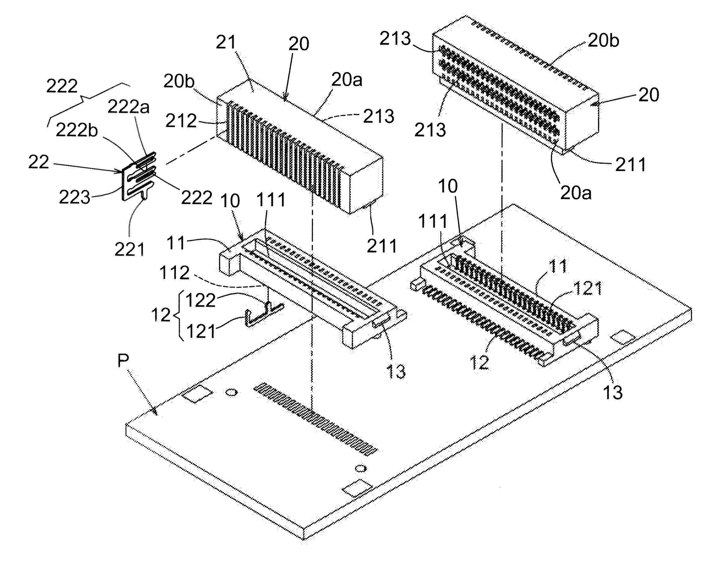
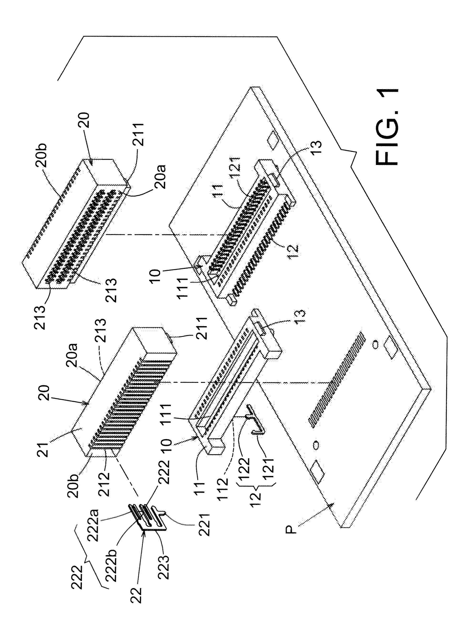
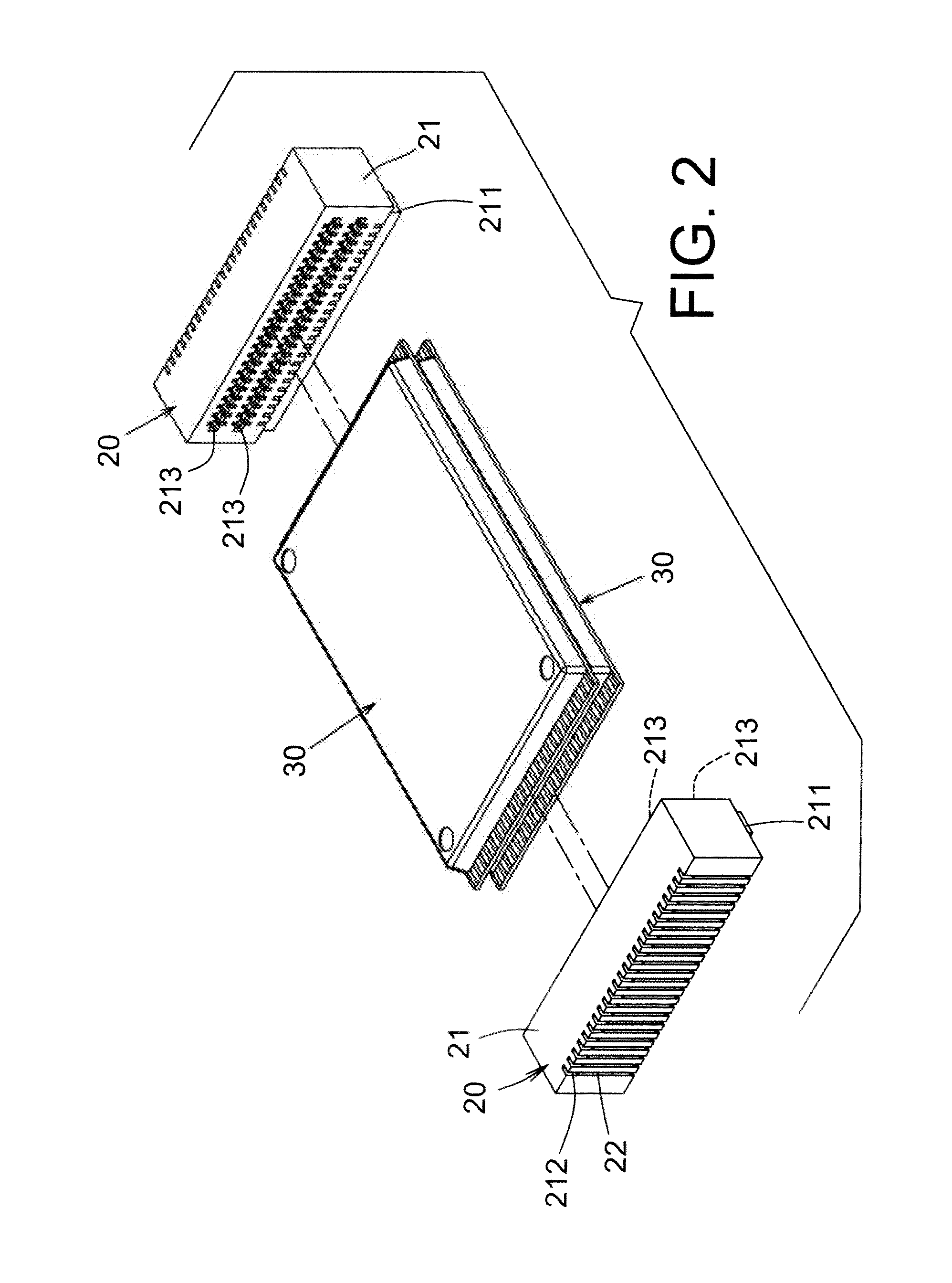
[0011]To achieve the above and other objects, the stacked multilayer connector of the present invention includes: two seat bodies oppositely disposed on a circuit board, each seat body having a main body section, a top face of the main body section being recessed to form a lengthwise connection slot, the main body section being further formed with multiple terminal passageways, a first terminal being inlaid in each of the terminal passageways, the first terminal having a projecting contact section extending into the connection slot of the main body section, a bottom section of the first terminal being soldered onto the circuit board; and two connection seats for holding opposite sides of multiple electronic card units in electrical contact with the contacts of the electronic card units. Each of the connection seats is formed with multiple sockets, whereby multiple electronic card units can be inserted into the sockets and stacked between the two connection seats and electrically connected with the connection seats. Each connection seat has an insulation main body. A bottom section of the insulation main body is formed with a projecting guide tenon, which can be correspondingly plugged into the connection slot of the seat body. The insulating main body is further formed with multiple terminal passages in which multiple second terminals are respectively correspondingly inlaid. Each of the second terminals has a contact arm extending along a lateral side of the guide tenon, whereby when the guide tenon is correspondingly inserted into the connection slot of the seat body, the contact arm comes into contact with one side of the contact section of the first terminal of the seat body. Each of the second terminals further has multiple electronic card contact sections in the form of stacked layers, the electronic card contact sections extending into the corresponding sockets respectively for contacting with multiple corresponding electronic card units layer by layer. Accordingly, multiple electronic card units can be previously held by means of the two connection seats and then the connection seats with the electronic card units can be plugged into the seat bodies at one time. In contrast, in the conventional multilayer electronic card connector, the connection seats must be insert-connected layer by layer and this often causes poor contact between the layers. Moreover, in the present invention, the contact arm of the second terminal is a projection below the electronic card contact sections. Due to such special structure, the width of the insulation main body of the connection seat can be reduced to minify the required installation space and lower manufacturing cost. Accordingly, the stacked multilayer connector of the present invention is applicable to lighter and slimmer electronic product.
[0012]According to the aforesaid, the stacked multilayer connector of the present invention has the following advantages:
[0013]1. In the stacked multilayer connector of the present invention, the connection seat is connected with the seat body at only one contact point. Therefore, the number of insert connection points of the stacked multilayer connector is greatly reduced to minimize the possibility of poor contact. In contrast, in the conventional multilayer electronic card connector, the connection seats must be insert-connected layer by layer and this often leads to poor contact between the layers.
[0014]2. In the stacked multilayer connector of the present invention, the volume of the connection seat is reduced to minify the required installation space and lower manufacturing cost. Accordingly, the stacked multilayer connector of the present invention is applicable to lighter and slimmer electronic product.

Problems solved by technology

In contrast, in the conventional multilayer electronic card connector, the connection seats must be insert-connected layer by layer and this often causes poor contact between the layers.

Method used


Image

  • Stacked multilayer connector
  • Stacked multilayer connector
  • Stacked multilayer connector

Examples


Embodiment Construction

[0026]Please refer to FIGS. 1 to 6. The stacked multilayer connector of the present invention includes two seat bodies 10 oppositely disposed on a circuit board P. Each seat body 10 has a main body section 11. A top face of the main body section 11 is recessed to form a lengthwise connection slot 111. In addition, the main body section 11 is formed with multiple terminal passageways 112 (with reference to FIG. 5). A first terminal 12 is inlaid in each of the terminal passageways 112. The first terminal 12 has a projecting contact section 121 extending into the connection slot 111 of the main body section 11. The bottom section of the first terminal 12 is soldered onto the circuit board P. The stacked multilayer connector of the present invention further includes two connection seats 20. Each of the connection seats 20 is formed with multiple, that is, two or more, sockets 213. The two connection seats 20 serve to hold opposite sides of multiple electronic card units 30 in electrical...


PUM


Abstract

A stacked multilayer connector includes two seat bodies oppositely disposed on a circuit board and two connection seats. Multiple electronic card units can be previously held between the connection seats as stacked layers and then the connection seats with the electronic card units can be plugged into the seat bodies into electrical contact with the circuit board. Each seat body has multiple terminal passageways in which multiple first terminals are inlaid. Each connection seat has multiple terminal passages in which multiple second terminals are inlaid. Each second terminal has multiple electronic card contact sections for clamping the electronic card units and a contact arm for contacting with the first terminal. The contact arm of the second terminal is a projection below the electronic card contact sections, whereby the width of the insulation main body of the connection seat is reduced to minify the required installation space and lower manufacturing cost.

Description

BACKGROUND OF THE INVENTION[0001]1. Field of the Invention[0002]The present invention relates to a stacked multilayer connector, and more particularly to a multilayer connector including two seat bodies and two connection seats. Multiple electronic card units can be previously held between the connection seats as stacked layers and then the connection seats with the electronic card units can be plugged into the seat bodies.[0003]2. Description of the Prior Art[0004]An existent stacked connector for connecting with multiple layers of electronic card units includes a pair of seat bodies and multiple pairs of connection seats. The seat bodies are oppositely soldered on a circuit board. An electronic card unit is previously held between a pair of connection seats and then the connection seats with the electronic card unit are plugged into the seat bodies or a lower pair of connection seats. Accordingly, the connection seats that hold the electronic card units are insert-connected and st...

Claims


Application Information

Patent Timeline
Patent Type & Authority Applications(United States)
IPC IPC(8): H01R12/14
CPCH01R13/112H01R12/716
Inventor LEE, IPSONCHEN, ANDY
Owner SUPER LINK ELECTRONICS
Why Eureka
Try Eureka