Flexible-client, flexible-line interface transponder

a client and line interface technology, applied in the direction of multiplex communication, time-division multiplex, electrical devices, etc., can solve the problems of increasing the overall complexity and cost of network operation, inability to achieve the rate adaptation flexibility at line interfaces, and limited existing technologies

Active Publication Date: 2015-06-25
NEC CORP
View PDF11 Cites 16 Cited by
  • Summary
  • Abstract
  • Description
  • Claims
  • Application Information

AI Technical Summary

Problems solved by technology

The rate adaptation flexibility at line interfaces therefore cannot be achieved until and unless the rate at client interfaces can be dynamically adapted.
However, existing technologies are limited in the granularity at which they can provide flexible client and line interfaces.
For example, using LAG and multiple WDM channels as described above, sub-wavelength granularity is not available and an operator has to manage a large number of channels to offer true flexibility, thus increasing the overall complexity and cost for operating the network.
Transponder architectures proposed so far that offer flexibility in the sub-wavelength granularity, for example the so-called multi-flow transponder architectures, make use of a large number of fixed-rate OTU framers and electro-optical modulators, thus leading to increased system cost.
At the same time, most existing commercial transponders do not demonstrate any of the aforementioned flexibility features, which may result to poor spectral efficiency performance for the routing and resource allocation process in networks making use of such transponders.
Moreover, existing transponder technologies do not allow disabling parts of the transponder.
As a result, they always operate at the maximum possible data rate, even though the actual data traffic that needs to be carried is less, hence demonstrating poor energy efficiency.

Method used


Image

  • Flexible-client, flexible-line interface transponder
  • Flexible-client, flexible-line interface transponder
  • Flexible-client, flexible-line interface transponder

Examples


Embodiment Construction

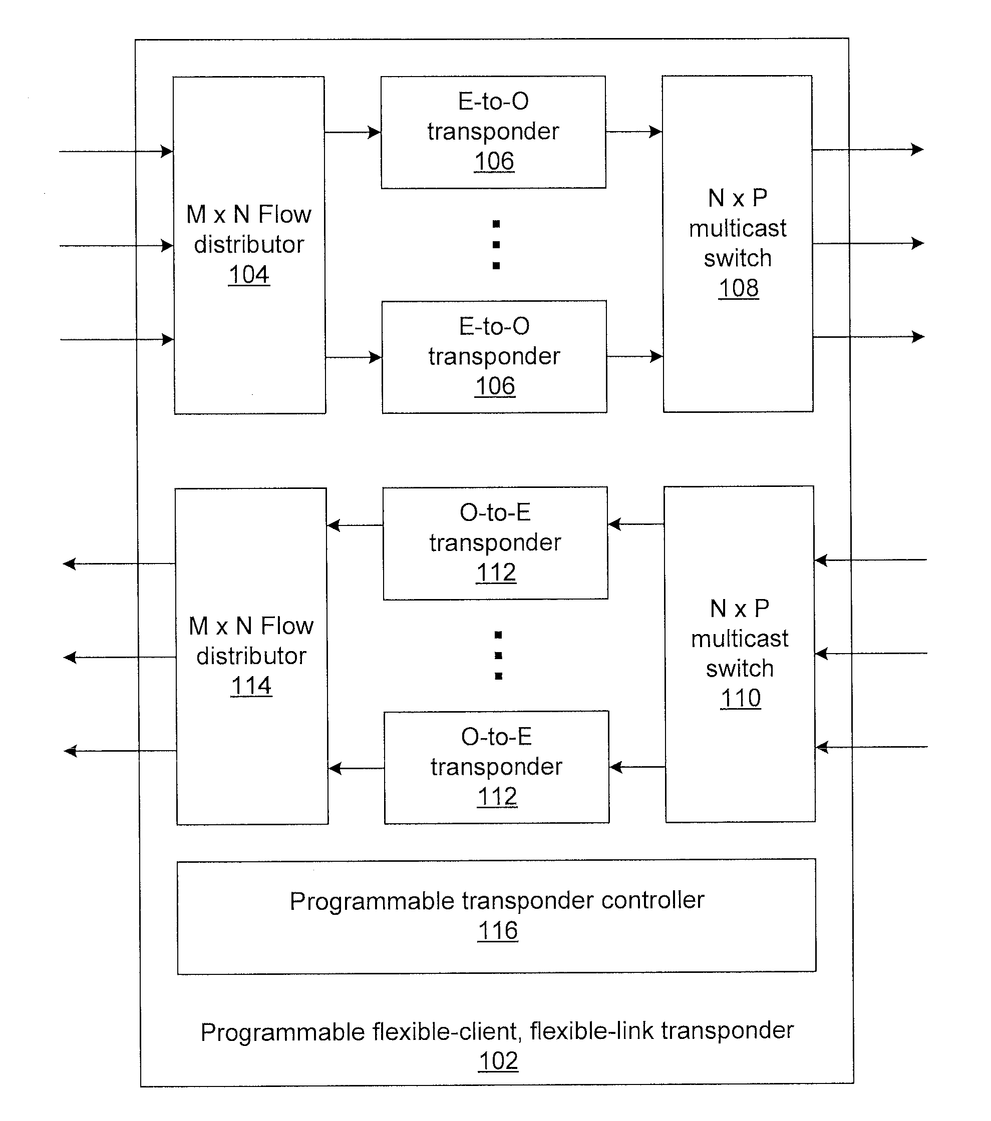
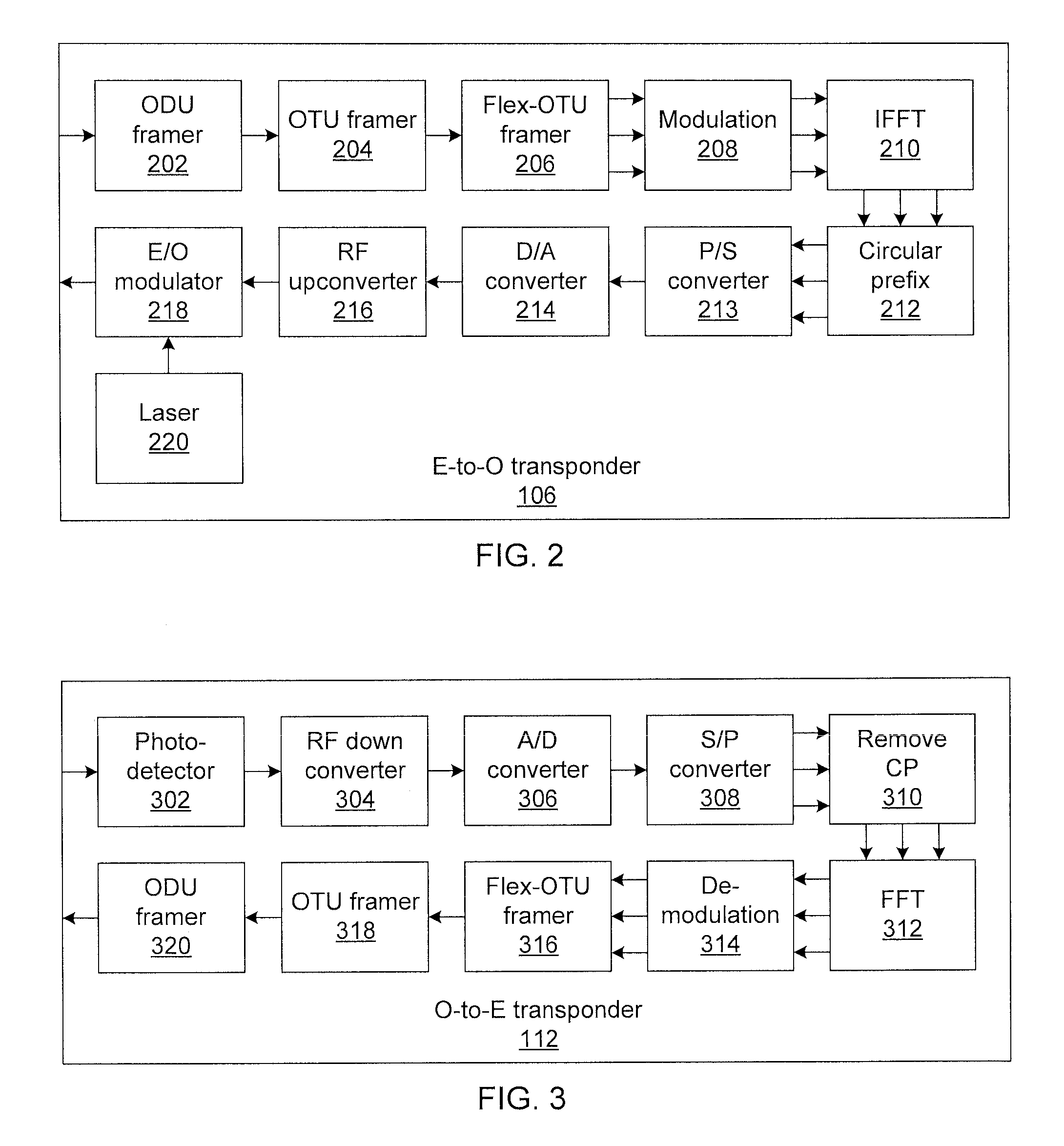
[0019]Embodiments of the present invention provide a flexible-client, flexible-line transponder in which flexible client and line interfaces are realized using frame compression, optical frequency division multiplexing (OFDM) modulation, and link aggregation groups (LAGs). Frame compression compresses optical transport network (OTN) frames by eliminating unused tributary slots during OTN framing. The compressed frame is then de-serialized and distributed among a number of physical lanes proportional to the actual data rate carried over the OTN channel. The bit streams over the physical lanes are modulated on independent subcarriers using electrical OFDM. Finally, the subcarriers are transmitted using a single wavelength division multiplexing channel (WDM). Thus, filtering out unused timeslots during framing and establishing electrical subcarriers proportional to the effective client rate enables flexible client interfaces. At the line interface, the line rate of a WDM channel can be...


PUM


Abstract

Methods and systems for flexible-client, flexible-link optical transponders include electrical-to-optical transponders, which accept client data from a flow distributor, and a first multiplexing switch that connects modulated optical carriers from the transponders to line interfaces. The electrical-to-optical transponders each include a flexible optical transport unit (OTU) framer module that compresses multiple optical data units (ODUs) into a single ODU having a higher order than any of the input ODUs to form an optical transport network (OTN) frame. An electrical-to-optical modulator modulates OTN frames onto a carrier. The transponder includes a second multiplexing switch that accepts optical carriers from line interfaces and optical-to-electrical transponders that accept modulated optical carriers from the second multiplexing switch. Each optical-to-electrical transponder includes a photodetector to convert the modulated optical carriers to the electrical domain and a flexible OTU framer module that decompresses received ODUs in OTN frames into multiple ODUs to form a bit stream.

Description

[0001]RELATED APPLICATION INFORMATION[0002]This application claims priority to provisional application Ser. No. 61 / 920,588, filed on Dec. 24, 2013, and the contents thereof are incorporated herein by reference.BACKGROUND OF THE INVENTION[0003]Software defined networks (SDNs) enable network programmability to support multi-vendor, multi-technology, multi-layer communications. Recently, efforts have been made to integrate optical transport within an IP / Ethernet-based SDN architecture to leverage optical transmission benefits such as low interference, long reach, and high capacity transmission with lower power consumption. Such networks are referred to as transport SDNs (T-SDNs). T-SDNs can be realized by enabling flexibility and programmability in transmission and switching network elements, such as transponders and reconfigurable optical add-drop multiplexers (ROADMs), management of optical channels such as by flexible-grid channel mapping, and extracting control plane intelligence f...

Claims


Application Information

Patent Timeline
Patent Type & Authority Applications(United States)
IPC IPC(8): H04Q11/00
CPCH04Q11/0062H04Q11/0005H04J3/1664H04J2203/0012H04J2203/0019
Inventor PATEL, ANKITKUMARKANONAKIS, KONSTANTINOSHU, JUNQIANGJI, PHILIP
Owner NEC CORP
Why Eureka
Try Eureka