

System and method for determining turbine degradation and mitigating turbine degradation in a variable geometry turbocharger
- Summary
- Abstract
- Description
- Claims
- Application Information
AI Technical Summary
Benefits of technology
Problems solved by technology
Method used
Image

Examples
Embodiment Construction
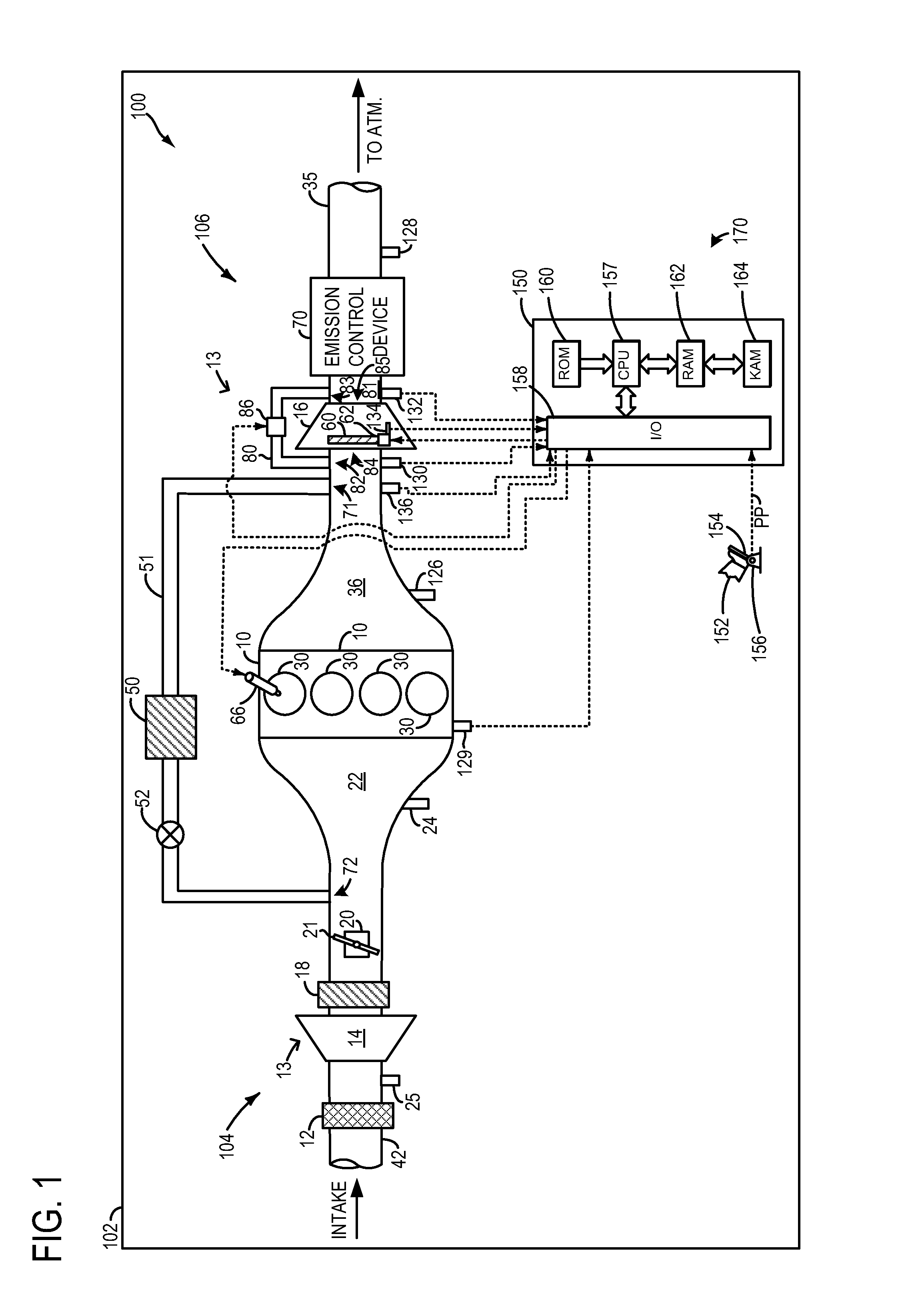
[0016]A system and method for determining and mitigating turbine degradation in a variable geometry turbocharger is described herein. Specifically, the system and method may be used to accurately determine turbine degradation based on a comparison of modeled and sensed pressure values both upstream and downstream of the turbine. In this way, a comparison of modeled pressures across the turbine and sensed pressures across the turbine may be used to increase the accuracy of a turbine degradation determination. Consequently, turbine degradation (e.g., malfunction) may be diagnosed over a wider range of engine operating conditions and more quickly, thereby improving turbine degradation diagnostics techniques in the vehicle system. Further in some examples, the method may additionally include, in response to determining the variable geometry turbine degradation, selecting one or more turbine degradation mitigation actions from a group of turbine degradation mitigation actions based on th...
PUM
 Abstract
Description
Claims
Application Information