Connector

a technology of connecting rods and connectors, applied in the direction of connection, electrical apparatus, coupling device connection, etc., can solve the problems of affecting the reliability of connection of terminals, and affecting the connection of terminals

Active Publication Date: 2015-12-24
YAZAKI CORP +1
View PDF4 Cites 3 Cited by
  • Summary
  • Abstract
  • Description
  • Claims
  • Application Information

AI Technical Summary

Benefits of technology

[0007]The present invention is devised by considering the above-described problems and a non-limited object of the present invention is to suppress a shift in a contact position of a connector terminal relative to a mating terminal due to a volume change of a connector housing.
[0009]According to the connector in the aspect of the present invention, since a variation of a position of the connector terminal due to the volume change of the connector housing at the time of a change of temperature can be reduced, a relative positional shift between the connector terminal and the mating terminal can be suppressed to stabilize a contact state of the terminals.

Problems solved by technology

When such a dimensional change arises, there is a fear that a contact position of the connector terminal and the mating terminal may be possibly shifted to deteriorate reliability in connection of the terminals.
Accordingly, a shift in the contact position of the terminals is liable to be large.
As a result, there is a fear that for instance, a friction arises between the terminals, so that plating on the surfaces of the terminals may possibly peel to cause rust in the connector terminal or increase an electric resistance to the mating terminal.

Method used


Image

  • Connector
  • Connector
  • Connector

Examples


Embodiment Construction

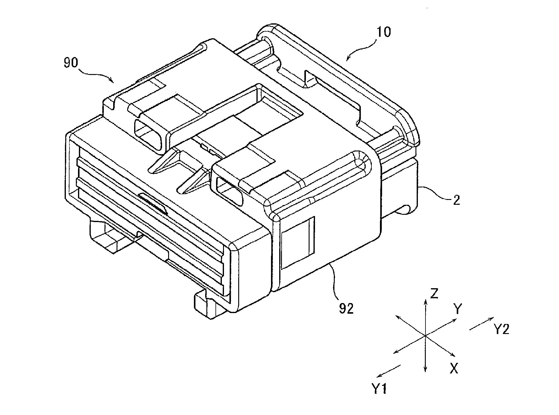
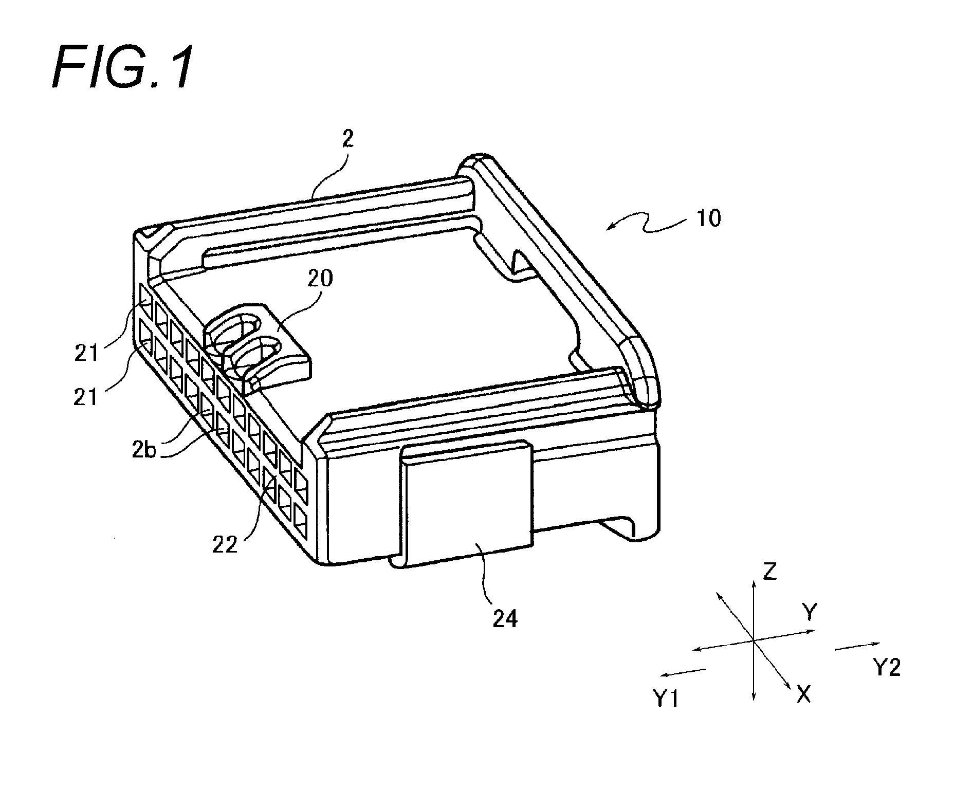
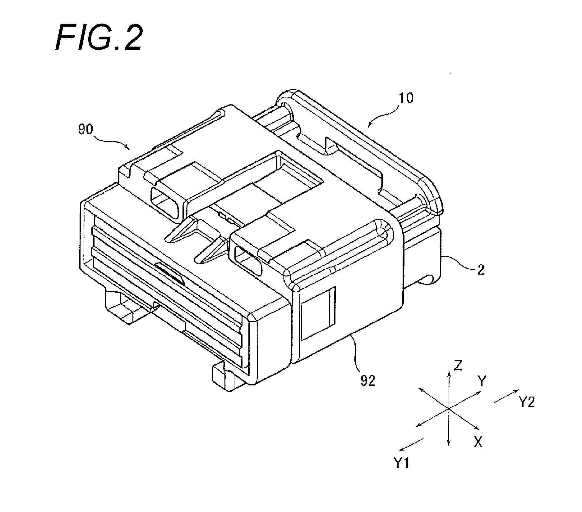
[0018]Now, a connector according to an exemplary embodiment of the present invention will be described below by referring to the accompanying drawings. FIGS. 1 to 3B show a structure of a connector 10 according to the one exemplary embodiment of the present invention. FIG. 1 is a perspective view showing an entire structure of the connector 10 according to the one exemplary embodiment of the present invention. FIG. 2 is a perspective view showing a state that the connector 10 is fitted to a mating component 90 to be connected. FIG. 3A is a longitudinally sectional view in such a fitted state, and FIG. 3B is a partially enlarged view of FIG. 3A. In a below-described explanation, a direction shown by an arrow mark X illustrated in FIGS. 1 to 3B is referred to as a transverse direction, a direction shown by an arrow mark Y is referred to as a longitudinal direction and a direction shown by an arrow mark Z is referred to as a vertical direction. The longitudinal direction thereof corres...


PUM


Abstract

A connector includes a connector housing including a locking mechanism which locks a mating housing and formed to be fitted to the mating housing, and a connector terminal held by the connector housing to come into contact with a mating terminal held by the mating housing. The connector housing is designed to have a locking position of the connector housing with the mating housing by the locking mechanism and a contact position of the connector terminal with the mating terminal, and the locking position and the contact position coincide with or come close to each other in a fitting direction relative to the mating housing.

Description

CROSS REFERENCE TO RELATED APPLICATIONS[0001]This application is based upon and claims the benefit of priority of Japanese Patent Application No. 2014-126069 filed on Jun. 19, 2014, the contents of which are incorporated herein by reference in its entirety.BACKGROUND OF THE INVENTION[0002]1. Field of the Invention[0003]The present invention relates to a connector which allows housings holding terminals to be fitted to each other so that the terminals are connected to each other.[0004]2. Description of the Related Art[0005]In a vehicle such as a motor vehicle, a connector is used which electrically connects a terminal connected to a plurality of electric wires of a wire harness to a mating component. The connector of this kind includes, for instance, a connector housing formed so as to be fitted to a mating housing which holds a mating terminal as a connection mate and one or a plurality of connector terminals which are held by the connector housing to come into contact with the mati...

Claims


Application Information

Patent Timeline
Patent Type & Authority Applications(United States)
IPC IPC(8): H01R13/627
CPCH01R13/6272H01R13/4223H01R13/193
Inventor TOYODA, RYOHEISAKAMOTO, NOBUYUKINAKASHIMA, TAKAHITO
Owner YAZAKI CORP
Why Eureka
Try Eureka