Force transmission device in particular for power transmission between a drive engine and an output

a transmission device and drive engine technology, applied in the direction of fluid couplings, couplings, gearing, etc., to achieve the effect of eliminating variations and reducing variations in the speed of rotation

Active Publication Date: 2012-04-24
SCHAEFFLER TECH AG & CO KG
View PDF7 Cites 151 Cited by
  • Summary
  • Abstract
  • Description
  • Claims
  • Application Information

AI Technical Summary

Benefits of technology

[0009]Thus it is the object of the invention to provide a force transmission device as recited supra, in particular a force transmission device with a multiple damper assembly, comprising at least two dampers connected in series viewed in at least one force flow direction in order to reduce variations in speed of rotation in the force transmission device over the entire operating range of the drive engine, or to eliminate the variations completely.

Problems solved by technology

However, also with these multiple dampers it is not possible without substantial additional complexity and partially also due to the limited installation space to cover the entire rotational speed range of a drive engine sufficiently with respect to vibration damping.

Method used


Image

  • Force transmission device in particular for power transmission between a drive engine and an output
  • Force transmission device in particular for power transmission between a drive engine and an output
  • Force transmission device in particular for power transmission between a drive engine and an output

Examples


Embodiment Construction

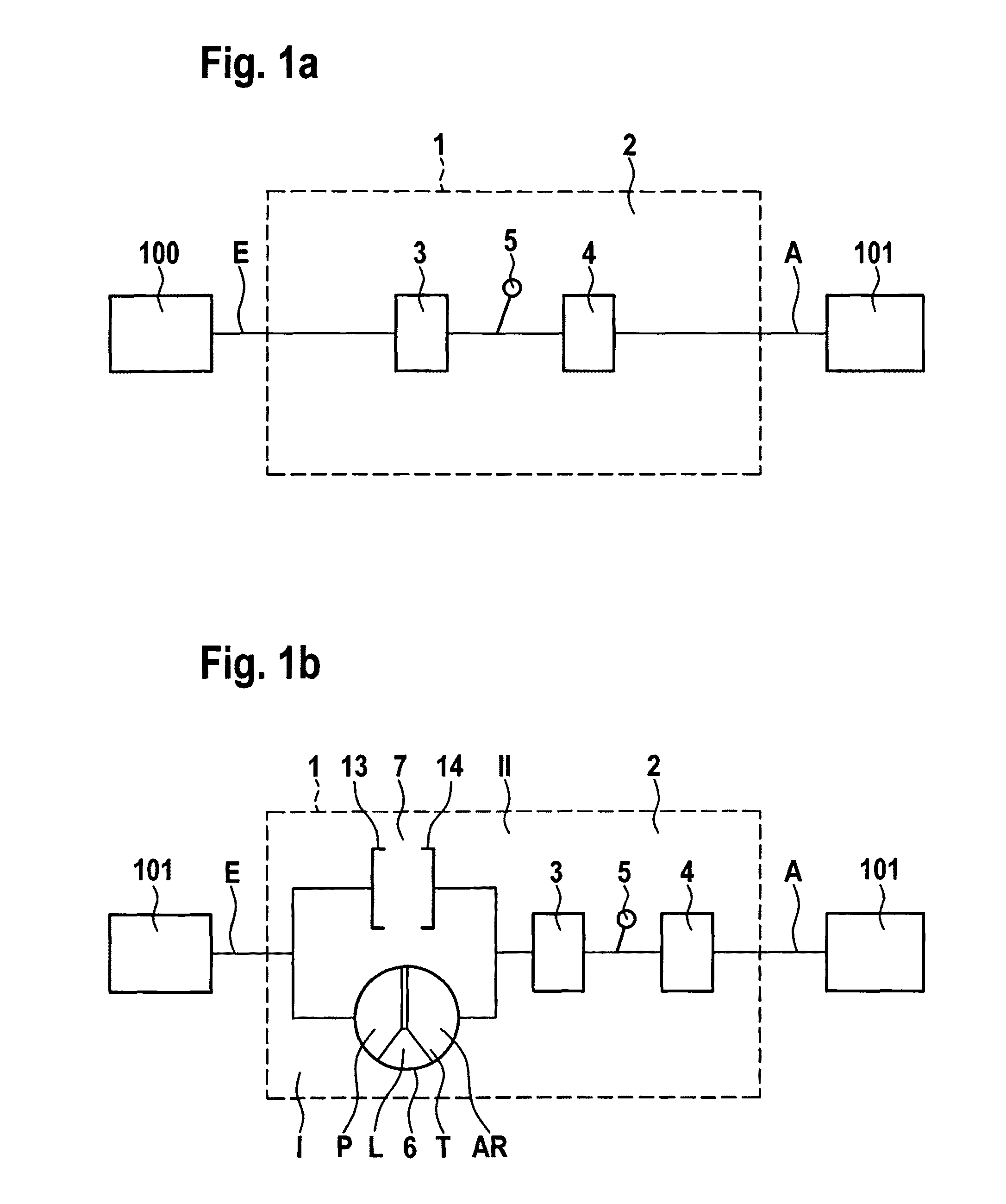
[0062]FIG. 1a illustrates the basic configuration of a force transmission device according to the invention in a simplified schematic depiction for power transmission in particular in drive trains of vehicles. Thus, the force transmission device 1 is used for power transmission between a drive engine 100 which can, for example, be configured as a combustion engine and an output 101. The force transmission device 1 includes at least an input E and an at least an output A. The input E is thus connected to the drive engine 100 at least indirectly, the output A is thus connected at least indirectly with the units 101 to be driven, for example, in the form of a transmission. “At least indirectly” thus means that the coupling is either performed directly, this means without additional transmission elements disposed there between, or indirectly through additional transmission elements. The terms “input” and “output” are thus to be interpreted in a functional manner in force flow direction ...


PUM


Abstract

A force transmission device, in particular or power transmission between a drive engine and an output, comprising a damper assembly with at least two dampers, which can be connected in series, and a rotational speed adaptive absorber, wherein the rotational speed adaptive tuned mass damper is disposed between the dampers at least in one force flow direction through the force transmission device.

Description

RELATED APPLICATIONS[0001]This patent application is a continuation of International patent application PCT / DE 2008 / 001900 filed on Nov. 17, 2008 claiming priority from and incorporating by reference German patent application DE 10 2007 057 448.9, filed on Nov. 29, 2007.FIELD OF THE INVENTION[0002]The invention relates to a force transmission device, in particular for power transmission between a drive engine and an output, the device including an input and an output and a damper assembly disposed between the input and the output, the damper assembly including at least two dampers which can be connected in series and a rotational speed adaptive absorber.[0003]Force transmission devices in drive trains between a drive engine and an output are known in the art in various configurations. When an internal combustion engine is used as a drive engine, a rotation occurs at the crankshaft, which superimposes the rotating motion, wherein the frequency of the rotation changes with the speed o...

Claims


Application Information

Patent Timeline
Patent Type & Authority Patents(United States)
IPC IPC(8): F16D3/14F16F15/10
CPCF16F15/145F16H2045/021F16H2045/0231F16H2045/0247F16H2045/0263F16H2045/0284Y10T74/2131Y10T74/2121
Inventor DEGLER, MARIOKRAUSE, THORSTENSCHENCK, KAIWERNER, MARKUSENGELMANN, DOMINIQUE
Owner SCHAEFFLER TECH AG & CO KG
Why Eureka
Try Eureka