Methods and apparatus for forming heat treated optical fiber

a technology of heat treatment and optical fiber, which is applied in the direction of applications, manufacturing tools, instruments, etc., can solve the problems of unsatisfactory defects such as heat aging, inability to meet the requirements of the treatment, and the refractive index profile of the fiber is not found, so as to achieve the best reduction of heat aging, increase rayleigh scattering, and maintain the effect of optical fiber within the treatment tension rang

Inactive Publication Date: 2009-07-28
CORNING INC
View PDF35 Cites 151 Cited by
  • Summary
  • Abstract
  • Description
  • Claims
  • Application Information

AI Technical Summary

Benefits of technology

[0004]Embodiments of the present invention provide methods and apparatus for forming an optical fiber, such as a doped optical fiber. As optical fiber is drawn from an optical fiber preform at certain draw speeds and draw tensions, undesirable defects such as heat aging defects are induced into the optical fiber. Likewise, certain draw conditions produce more micro-scale density variations that lead to increased Rayleigh scattering. To combat these defects, the optical fiber is treated in accordance with the invention by maintaining the optical fiber within a treatment temperature range for a treatment time. In particular, it is desired to subject the optical fiber, as drawn, ...

Problems solved by technology

As optical fiber is drawn from an optical fiber preform at certain draw speeds and draw tensions, undesirable defects such as heat aging defects are induced into the optical fiber.
In parti...

Method used


Image

  • Methods and apparatus for forming heat treated optical fiber
  • Methods and apparatus for forming heat treated optical fiber
  • Methods and apparatus for forming heat treated optical fiber

Examples


example 1

[0064]Using a draw furnace, a negative dispersion germania-doped optical fiber having a profile including a core and a ring as shown in FIG. 5 was drawn from a doped preform at a rate of 14 meters per second (m / s) with a tension of 150 grams. Thereafter, the fiber was cooled to 20° C. and then subjected to the heat aging test as described above. Following this test, the measured attenuation increase in the untreated fiber at 1550 nm was 0.0830 dB / km.

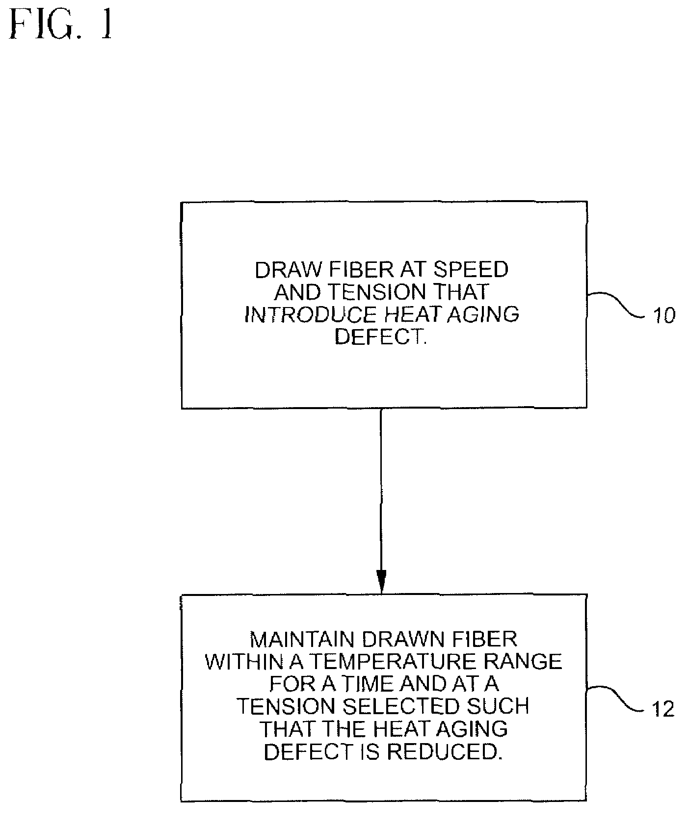
[0065]A second fiber was drawn from an identical preform in the same manner as described just above. The second fiber was passed through a treatment apparatus in accordance with the invention as described in FIG. 4 immediately after the fiber exited the draw furnace. The length and operating parameters of the treatment furnace were selected such that the temperature of the second fiber was maintained at a desired temperature for a desired amount of time. In particular, the length M of passage was about 0.615 m. Thus, the fiber was mainta...

example 2

[0066]Using a draw furnace, a negative dispersion germania and fluorine doped optical fiber having a profile including a core, moat and a ring as shown in FIG. 6 was drawn from a preform at a rate of 14 meters per second (m / s) with a tension of 150 grams. Thereafter, the fiber was cooled to 20° C. and then subjected to the heat aging test as described above. Then testing revealed that the measured attenuation increase in the fiber at 1550 nm was 0.285 dB / km following heating for 20 hours at 200° C.

[0067]A second fiber was drawn from an identical preform in the same manner as described just above. The second fiber was subjected to the treatment apparatus and method in accordance with the invention described in FIG. 4 herein immediately after the fiber exited the draw furnace. The length and operating parameters of the treatment furnace were selected such that the temperature of the second fiber was maintained at the conditions identified in Example 1. Thereafter, the fiber was cooled...

example 3

[0068]Using a draw furnace, a germania and fluorine doped silica glass optical fiber having a negative dispersion and dispersion slope and a profile as shown in FIG. 5 was drawn from a preform at a rate of 14 meters per second (m / s) with a tension of 150 grams. A helium forming gas was used in the draw furnace. Thereafter, the fiber was cooled to 20° C. and then subjected to the heat aging testing where the fiber is maintained at 200° C. for 20 hours. At the end of this period, the fiber was cooled to 20° C., the measured attenuation increase in the fiber at 1550 nm was 0.420 dB / km.

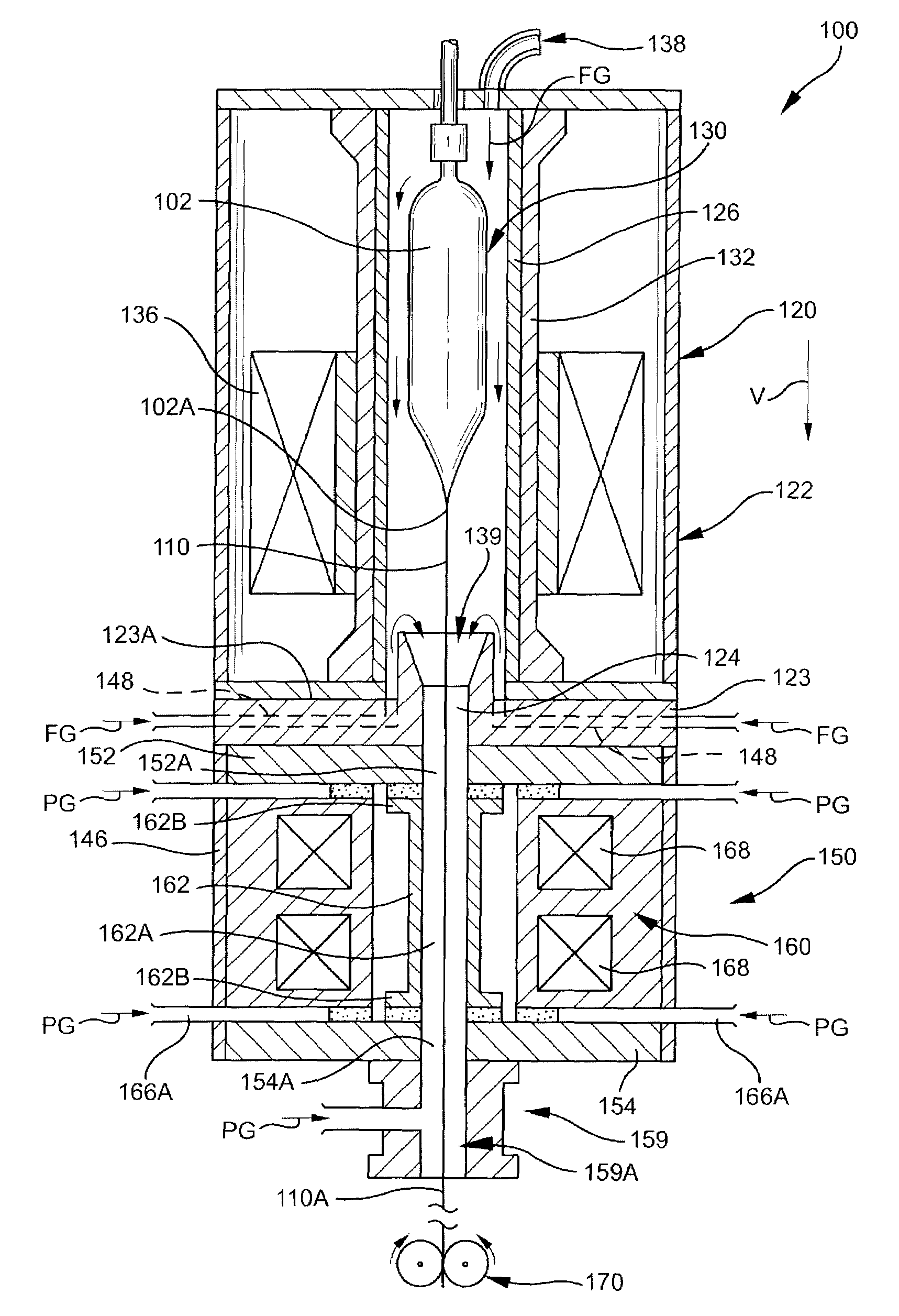
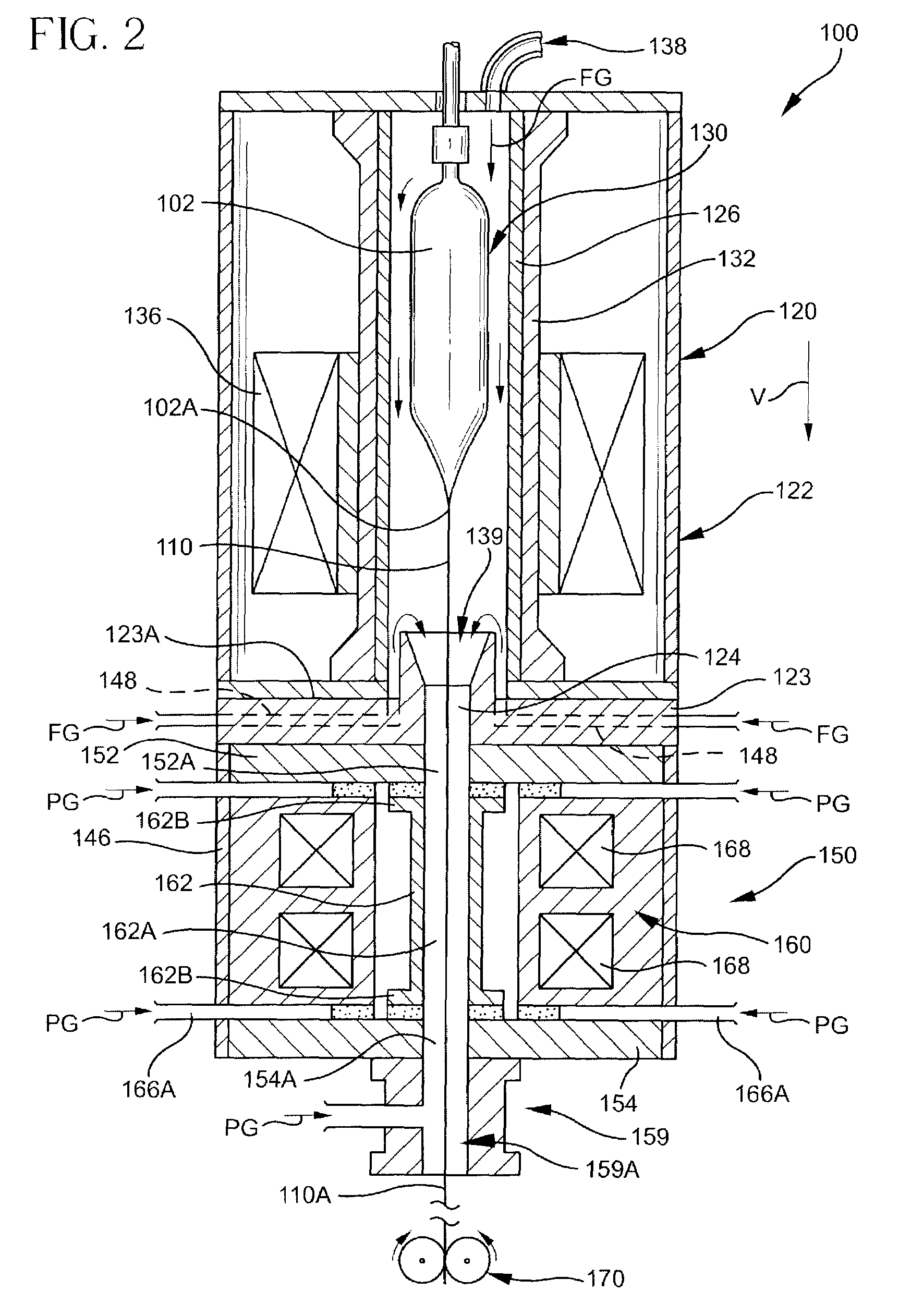
[0069]A second fiber was drawn in the same manner as described just above from an identical fiber. The second fiber was passed through a heated treatment apparatus as shown in FIG. 2 immediately after the fiber exited the draw furnace. The length of the muffle was 0.4 m and its inside diameter was 60 mm and the temperature was selected such that the temperature of the second fiber was maintained at from a...


PUM

PropertyMeasurementUnit
Temperatureaaaaaaaaaa

Abstract

A method for forming an optical fiber includes drawing the optical fiber from a glass supply and treating the fiber by maintaining the optical fiber within a treatment temperature range for a treatment time. Preferably also, the fiber is cooled at a specified cooling rate. The optical fiber treatment reduces the tendency of the optical fiber to increase in attenuation due to Rayleigh scattering, and/or over time following formation of the optical fiber due to heat aging. Apparatus are also provided.

Description

RELATED APPLICATIONS[0001]The present invention is a continuation-in-part application that claims priority to, and the benefit of, U.S. patent application Ser. No. 10 / 136,697 filed Apr. 30, 2002.FIELD OF THE INVENTION[0002]The present invention relates to methods and apparatus for forming optical fiber and, more particularly, to methods and apparatus for forming optical fiber having improved characteristics.BACKGROUND OF THE INVENTION[0003]Attenuation and sensitivity to heat (or thermal) aging may be critical attributes of optical fibers, particularly for high data rate optical fibers. In making optical fibers, it may be necessary or desirable to minimize attenuation loss in the intended window of operation for the fiber. Attenuation in an optical fiber can increase after fabrication of the fiber because of a phenomenon called “heat aging.” Heat aging is the tendency of some optical fibers to increase in attenuation over time following formation of the fibers due to temperature fluc...

Claims


Application Information

Patent Timeline
IPC IPC(8): C03B37/07C03B37/027
CPCC03B37/02718C03B2205/55C03B2205/42C03B2203/36Y02P40/57
Inventor FOSTER, JOHN D.MATTHEWS, III, HAZEL B.
Owner CORNING INC
Why Eureka
Try Eureka