Media filter assembly having replaceable filter element

a filter element and filter assembly technology, applied in the field of filter assembly, can solve the problems of inability to replace the filter element, the central forced air system is harder and less efficient, and the indoor air quality suffers, so as to achieve the effect of improving seal and substantial structural integrity

Inactive Publication Date: 2001-07-24
SKUTTLE MFG
View PDF3 Cites 120 Cited by
  • Summary
  • Abstract
  • Description
  • Claims
  • Application Information

AI Technical Summary

Benefits of technology

It is still a further aspect of the present invention to provide a filter assembly having an improved filter cover design, as above, wherein the filter cover exhibits substantial structural integrity and provides an improved seal between the filter cover and the filter element retained within the filter housing.

Problems solved by technology

One draw back of such weather tight building designs is that indoor air quality suffers.
For obvious reasons, it is undesirable to have high concentrations of particulates, such as dust, pollen and smoke within a building.
After an extended period of use, the accumulation of airborne particulates on the media filter begins to restrict air flow through the return air duct, making the central forced air system work harder and less efficiently.
It is very important that these screws do not come into contact with the media filter element within the housing because airborne particles will seek out the path of at least resistance through the filter media and, therefore, any puncture, tear, or hole in the media filter will compromise the filter's efficiency.
However, in these prior art devices, the size of the screw that may be used to install the housing is limited by the size of the channel, at least when the screw is being inserted into the channel towards the portion of the L-shaped guide member directly abutting the filter element.
These channels also limit the means by which the filter housing may be installed because they block off internal access to portions of the filter housing thereby requiring that the installment screws be attached to the housing from the outside in.
Therefore, the placement of installation screws is substantially limited in that screws can only be placed near the edges of the filter housing because placement outside this area, such as at the middle of the top or bottom wall, would cause the screw to puncture the filter element which directly abuts that area.
From a manufacturing standpoint, each extra member or structural item that makes up the filter assembly as a whole increases the complexity in assembling the finished product.
Also, it should be realized that each individual structural item secured to create the finished filter assembly introduces an attachment means which may fail and thereby compromises the structural integrity of the filter assembly.
As such, the structural integrity of the filter cover is questionable, as is the seal that the filter cover creates between the filter cover and the filter element placed within the filter housing.

Method used


Image

  • Media filter assembly having replaceable filter element
  • Media filter assembly having replaceable filter element
  • Media filter assembly having replaceable filter element

Examples


Embodiment Construction

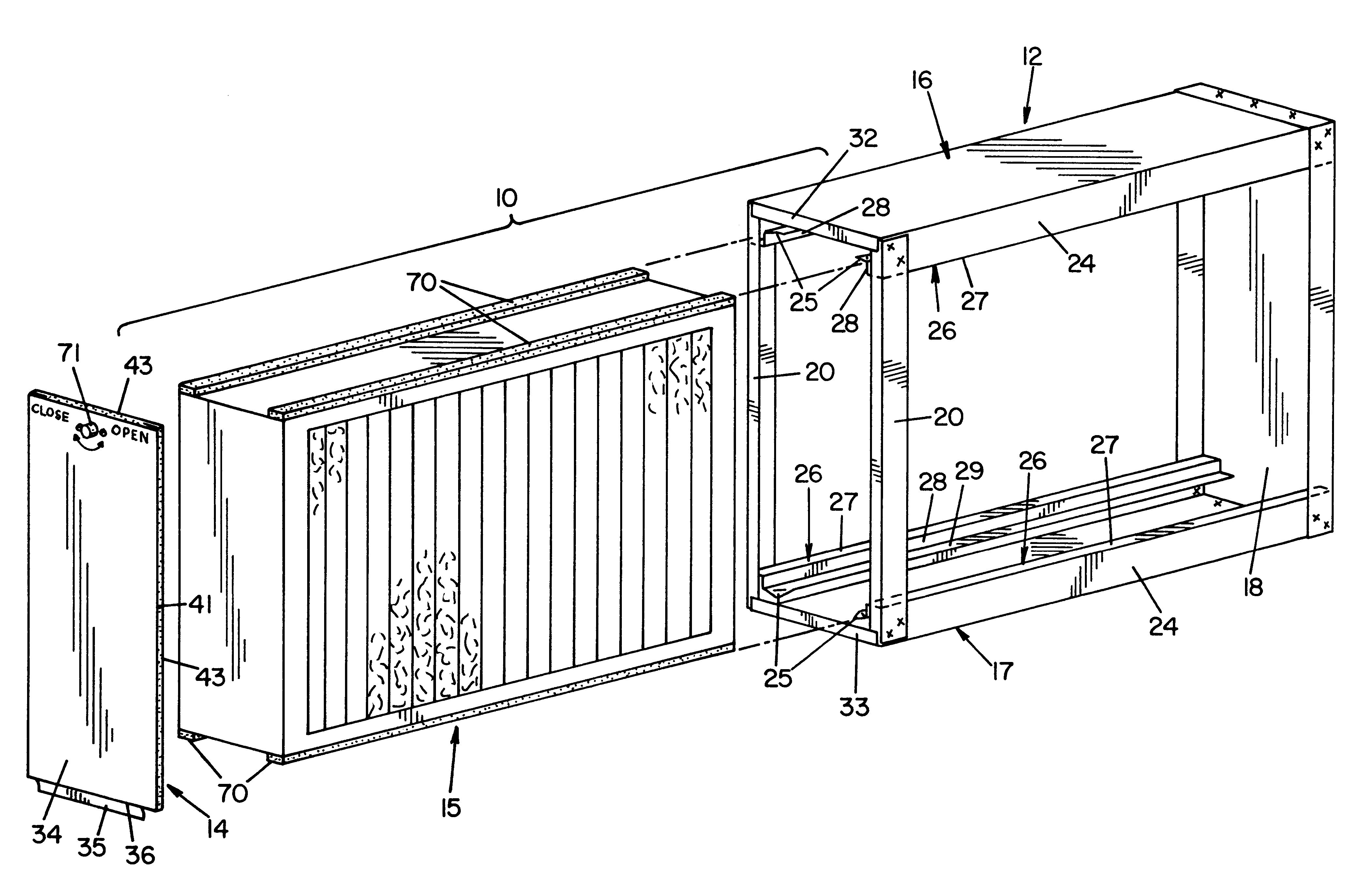
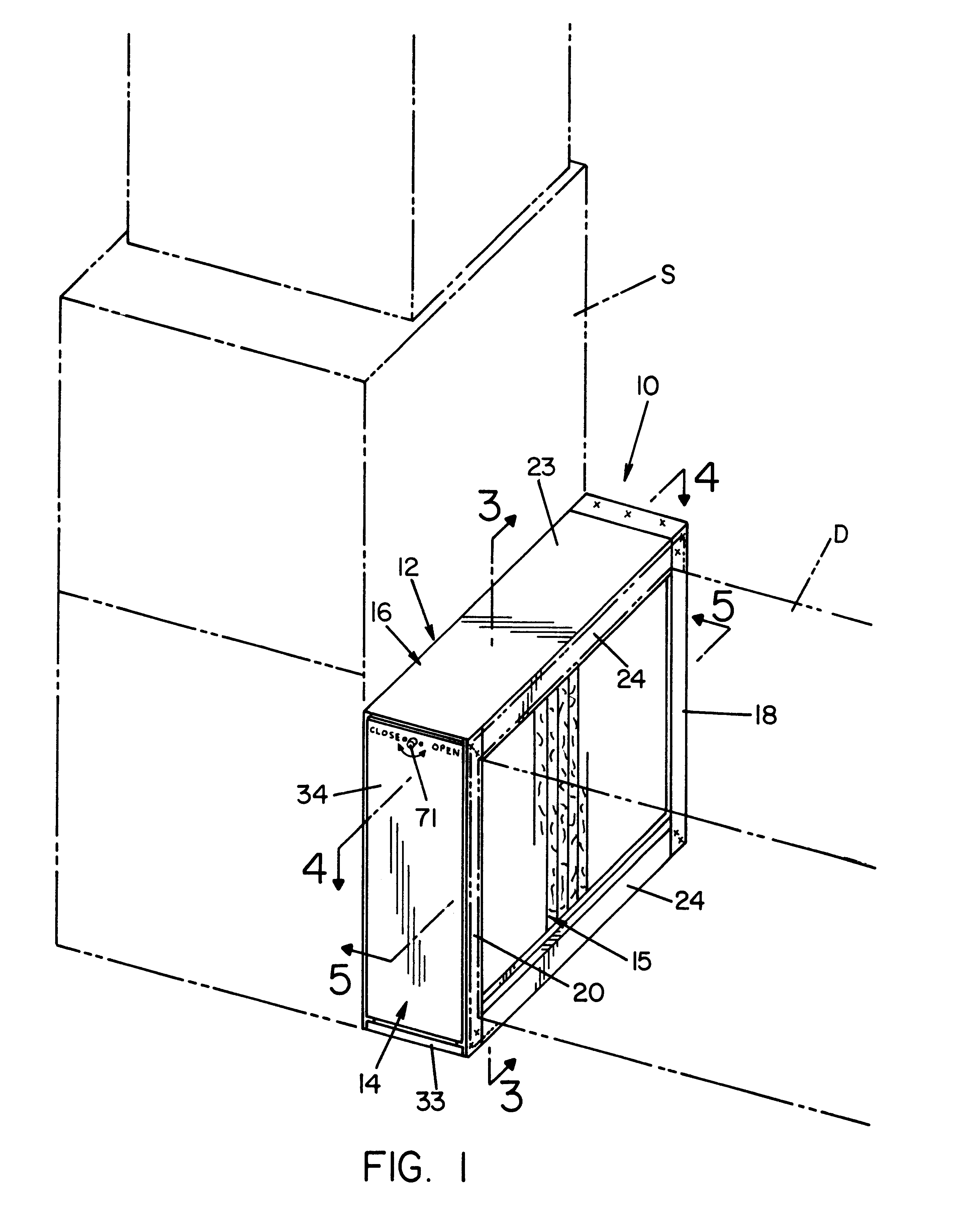
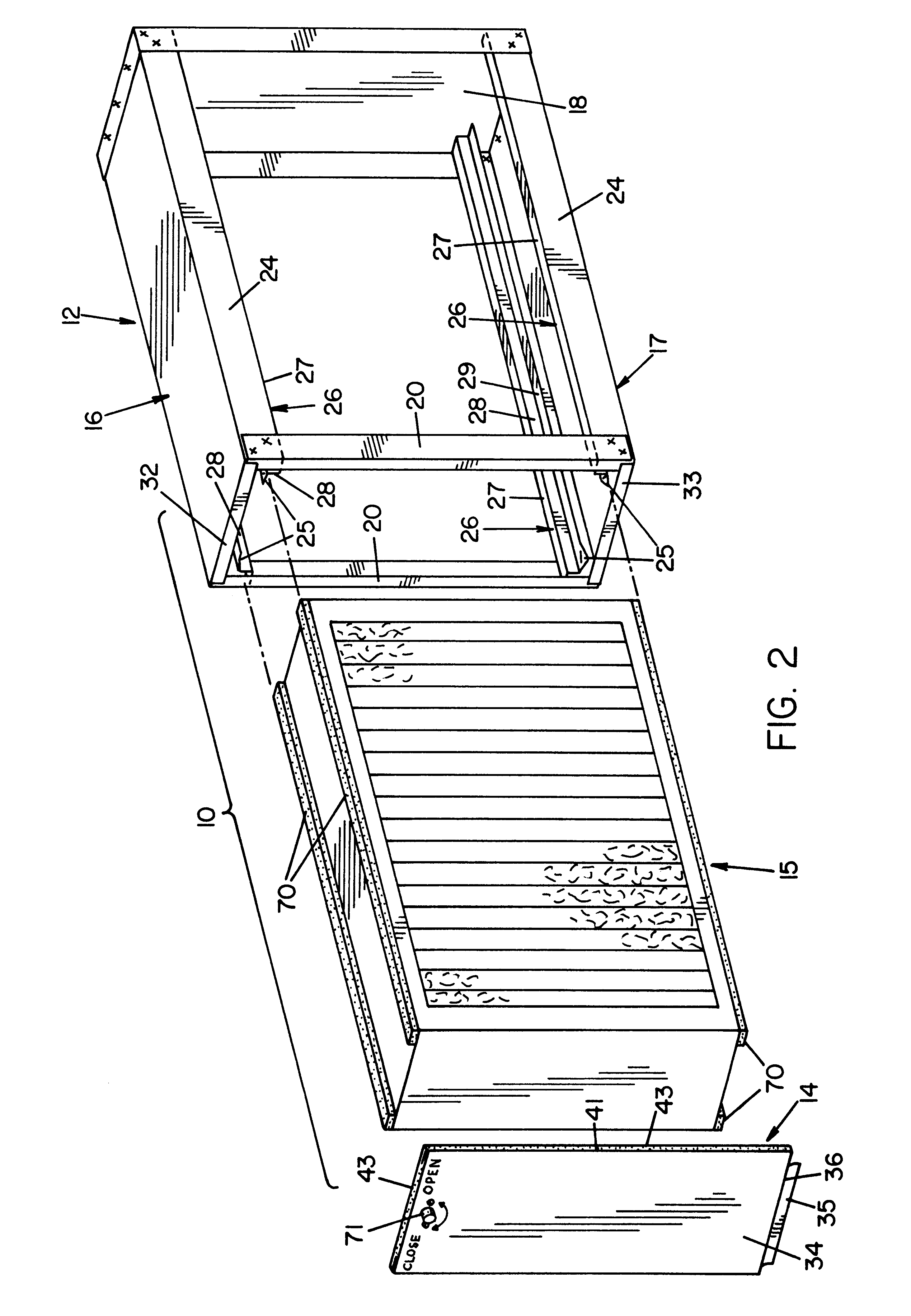
As noted hereinabove, the present invention is directed toward the construction of an air filter assembly for use preferably in a return air duct of a forced air system. One representative embodiment of a filter assembly according to the concepts of the presents invention is designated generally by the numeral 10 in FIGS. 1 and 2. With particular reference to FIG. 2, it can be seen that filter assembly 10 includes a filter housing 12 and a filter cover 14 that serve to retain filter element 15 within the filter housing 12. Filter element 15 is retained across the pathway of air traveling in the direction shown by the arrows in FIGS. 3 and 4 through a return air duct D towards a central forced air system S. As those skilled in the art will appreciate, the orientation of filter assembly 10 in FIG. 1 represents just one of various positions that filter assembly 10 may occupy in a return air duct. Regardless of the type of installation practiced, filter housing 12 is securely fastened t...


PUM

PropertyMeasurementUnit
areasaaaaaaaaaa
lengthaaaaaaaaaa
concentrationsaaaaaaaaaa

Abstract

A filter assembly is provided having a housing and a cover that communicate to retain a filter element. The housing has a top and a bottom spaced apart from each other, and a first pair of guide members is maintained beneath the top while a second pair of guide members is maintained above the bottom. The filter element is retained in the housing between the first and second pair of guide members thereby defining a first cavity between the top and the filter element and a second cavity between the bottom and the filter element. Fasteners, such as screws, rivets, nails and the like, may communicate with the cavities without damaging the filter element. The first and second pair of guide members allow for access to the internal surface area of the top and bottom of the housing such that fasteners or other installment means can be employed from the inside of the housing outwardly to the duct work or framework to which the filter assembly is to be attached.

Description

The present invention relates generally to air filter systems. More particularly, the present invention relates to a media filter assembly or cabinet having an improved design for simplifying installation and minimizing maintenance of the system.Central forced air systems are commonly used to heat and cool residential and commercial buildings. These systems force air from a central furnace or air conditioner through duct work that carries the air to various rooms or areas of the building. In order for these systems to work efficiently, it is important to minimize the transfer of air between the inside and outside of the building. One draw back of such weather tight building designs is that indoor air quality suffers. Airborne particles are trapped inside the building and accumulate such that the air in today's buildings may be anywhere from 20 to 100 times more polluted than the outdoor air. For obvious reasons, it is undesirable to have high concentrations of particulates, such as ...

Claims


Application Information

Patent Timeline
Patent Type & Authority Patents(United States)
IPC IPC(8): B01D46/42B01D46/52B01D46/00B01D46/10
CPCB01D46/0005B01D46/521B01D46/10B01D46/008B01D46/88
Inventor LEWIS, II, EARL K.
Owner SKUTTLE MFG
Why Eureka
Try Eureka