Connector brackets

a technology of connecting brackets and brackets, which is applied in the direction of elevators, transportation and packaging, etc., can solve the problems of affecting the installation effect of the prior art,

Inactive Publication Date: 2004-12-14
SNEED TERRYLE L
View PDF12 Cites 17 Cited by
  • Summary
  • Abstract
  • Description
  • Claims
  • Application Information

AI Technical Summary

Benefits of technology

Another object of the invention is to provide a novel method and apparatus for quickly, easily, and adjustably connecting elevator car and counterweight guide rail support brackets to the sidewalls of an elevator hoistway of a building.
Another object of the invention is to provide an apparatus as described in the preceding paragraphs that includes specially configured connector bolts that provide substantial structural integrity and positively preclude shifting of the brackets even as a result of projected seismic loading.

Problems solved by technology

This prior art installation technique is both cumbersome and time consuming even in new construction.
However, in retrofit constructions, the technique is particularly difficult.
For example, when the elevator systems in hospitals, schools, and other public buildings are retrofitted, the welding step is quite hazardous and most undesirable.
This is because, during the retrofit operations, welding of the rail brackets to the support brackets results in noxious welding gases and fumes unavoidably spreading throughout the building.
Particularly in hospitals and schools, these noxious welding gases can be both unpleasant and hazardous and can, on occasion, result in serious complications to the persons exposed to the noxious fumes.

Method used


Image

  • Connector brackets
  • Connector brackets
  • Connector brackets

Examples


Embodiment Construction

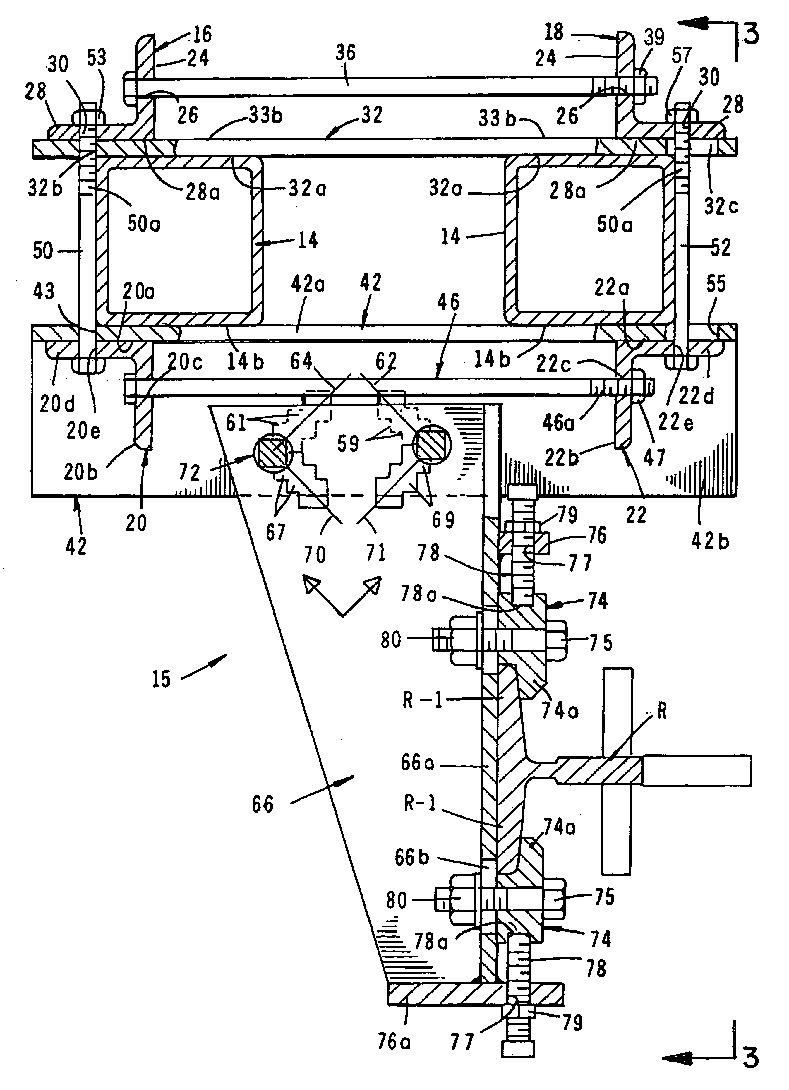
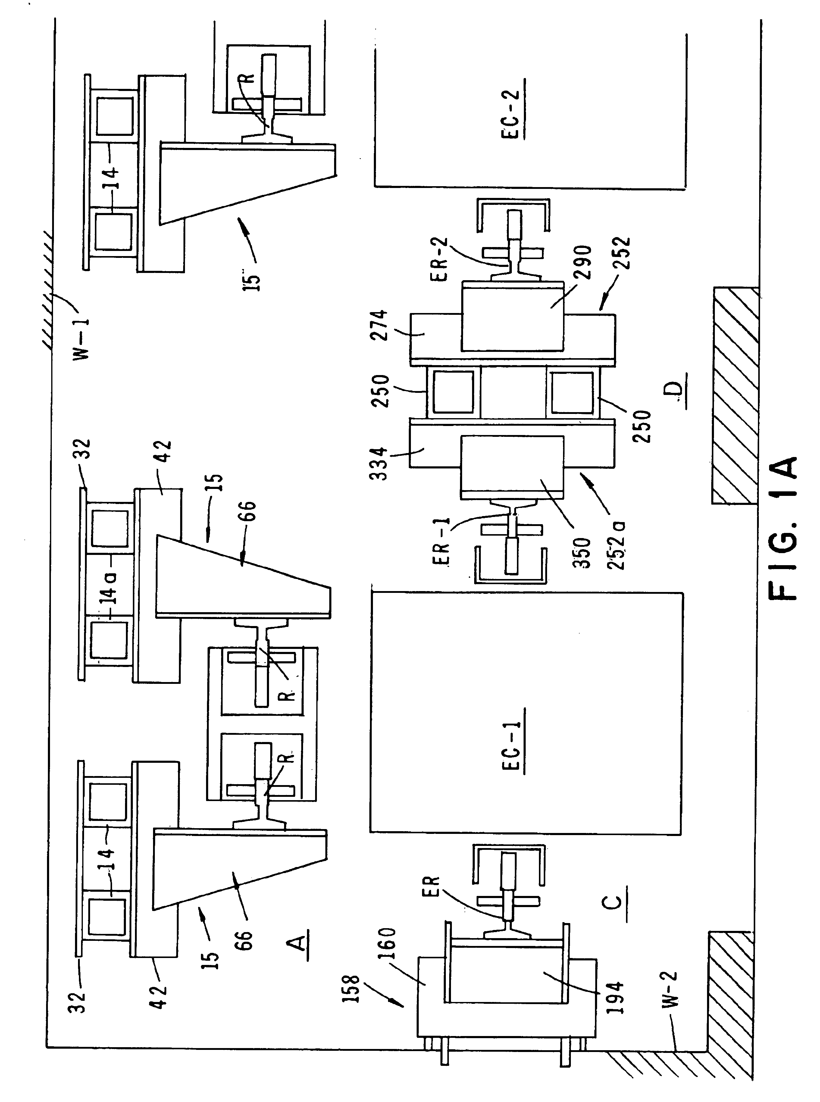
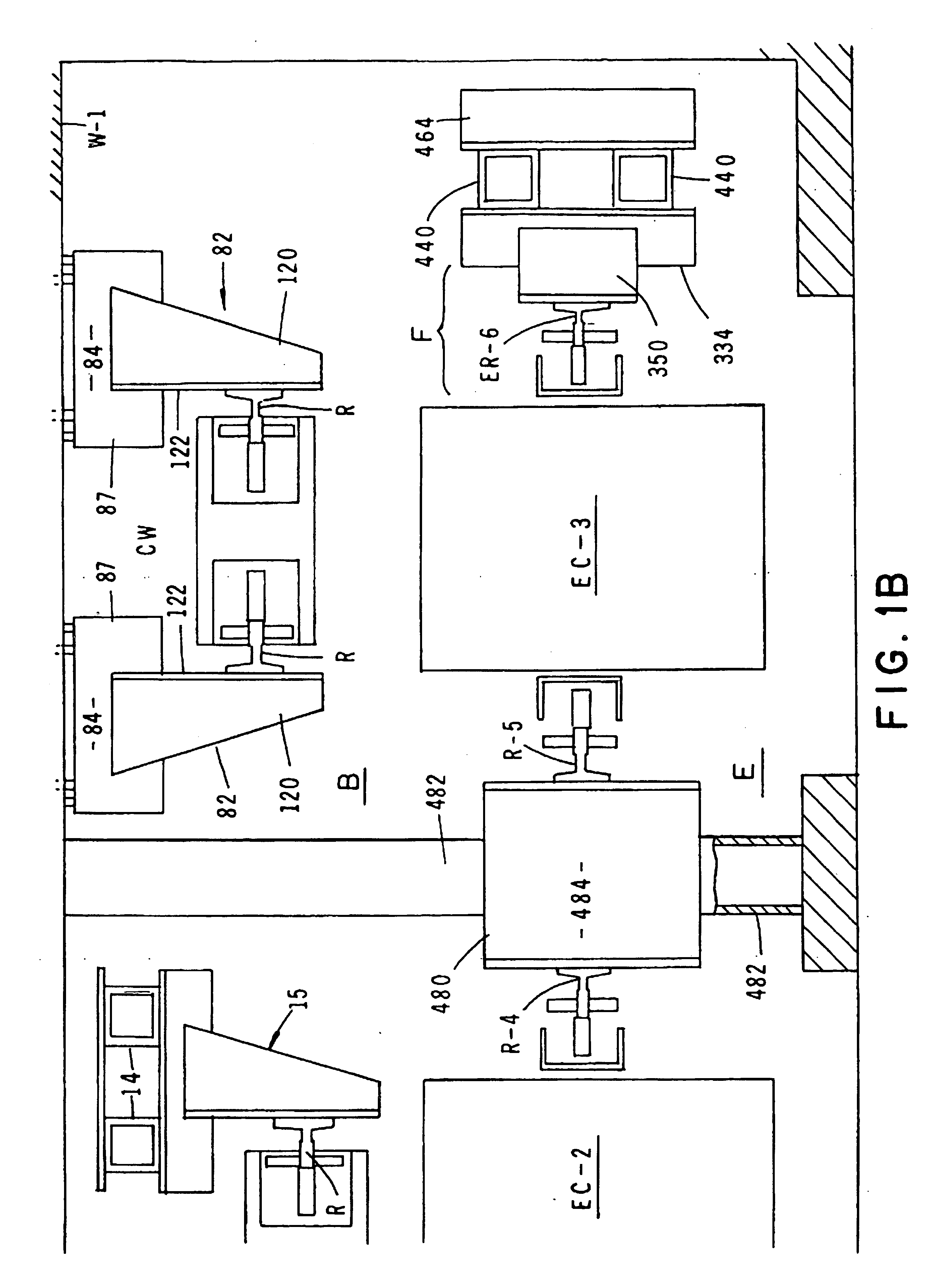
Referring to the drawings and particularly to FIGS. 1A and 1B, several forms of the connector apparatus of the present invention for interconnecting guide rails in elevator systems with various types of structural components is there illustrated. In the area of FIG. 1A designated by the letter A, a connector apparatus for interconnecting the guide rails of a counterweight system with two pair of vertically extending columns is there illustrated. Shown in the area designated by the letter B in FIG. 1B is a connector apparatus for interconnecting the guide rails of a counterweight system with one wall of the building structure that houses the elevator system. In the area of FIG. 1A designated by the letter C there is shown a connector apparatus for interconnecting a guide rail of an elevator system with one wall of the building structure that houses the elevator system. In the area designated by the letter D in FIG. 1A is a connector apparatus for interconnecting the guide rails of an...


PUM


Abstract

An apparatus for quickly, easily and adjustably connecting elevator car and counterweight guide rail support brackets to the walls of an elevator hoistway and also to either vertically or horizontally extend structural beams that are disposed within the elevator hoistway. Installation of the apparatus requires no welding operations to be performed in order to connect the brackets to the walls or to the beams. The apparatus uniquely includes cooperating support and connector brackets each of which has a plurality of strategically arranged, indexable connector holes that permit the necessary degree of adjustment of the brackets to properly position the guide rails within the hoistway.

Description

1. Field of the InventionThe present invention relates to a method and apparatus for mounting within an elevator shaft counterweight rails or guide rails for elevator cars. More particularly, the invention concerns a mounting system in which the guide rails are adjustably attached to one or more intermediate beams that are disposed within the elevator shaft.2. Discussion of the Prior ArtA typical prior art electric power elevator system has an elevator shaft or hoistway within which guide rails are mounted to guide the vertical travel of elevator cars and counterweights. In many instances in prior art construction, intermediate beams are used to divide an elevator shaft into two or more parts forming channels for separate cars moving along guide rails attached to intermediate beams. Guide rails for counterweights can also be mounted on the intermediate beams.In the past, the guide rails for elevator cars or counterweights were secured to the intermediate beams using various bars and...

Claims


Application Information

Patent Timeline
Patent Type & Authority Patents(United States)
IPC IPC(8): B66B7/02
CPCB66B7/024B66B7/02
Inventor SNEED, TERRYLE L.
Owner SNEED TERRYLE L
Why Eureka
Try Eureka