
Water current powered generating apparatus

a technology of generating apparatus and water current, which is applied in the direction of wind motors with perpendicular air flow, electric generator control, machines/engines, etc., can solve the problems of large equipment costs, inability to effectively realize wave-powered generating apparatuses, and inability to meet the needs of the user

Active Publication Date: 2012-09-25
SCOTRENEWABLES MARINE POWER
View PDF9 Cites 14 Cited by
  • Summary
  • Abstract
  • Description
  • Claims
  • Application Information

AI Technical Summary

Benefits of technology

[0006]It is an object of the present invention to avoid or minimise one or more of the foregoing disadvantages.
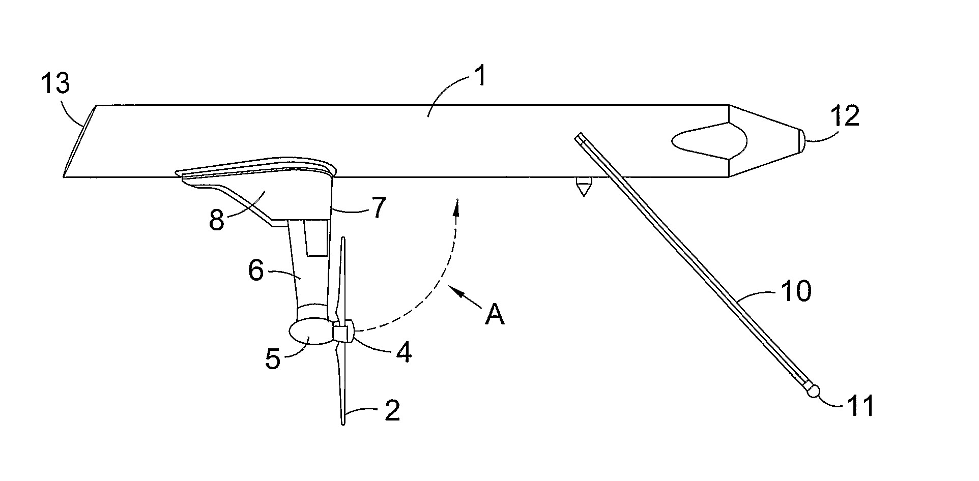
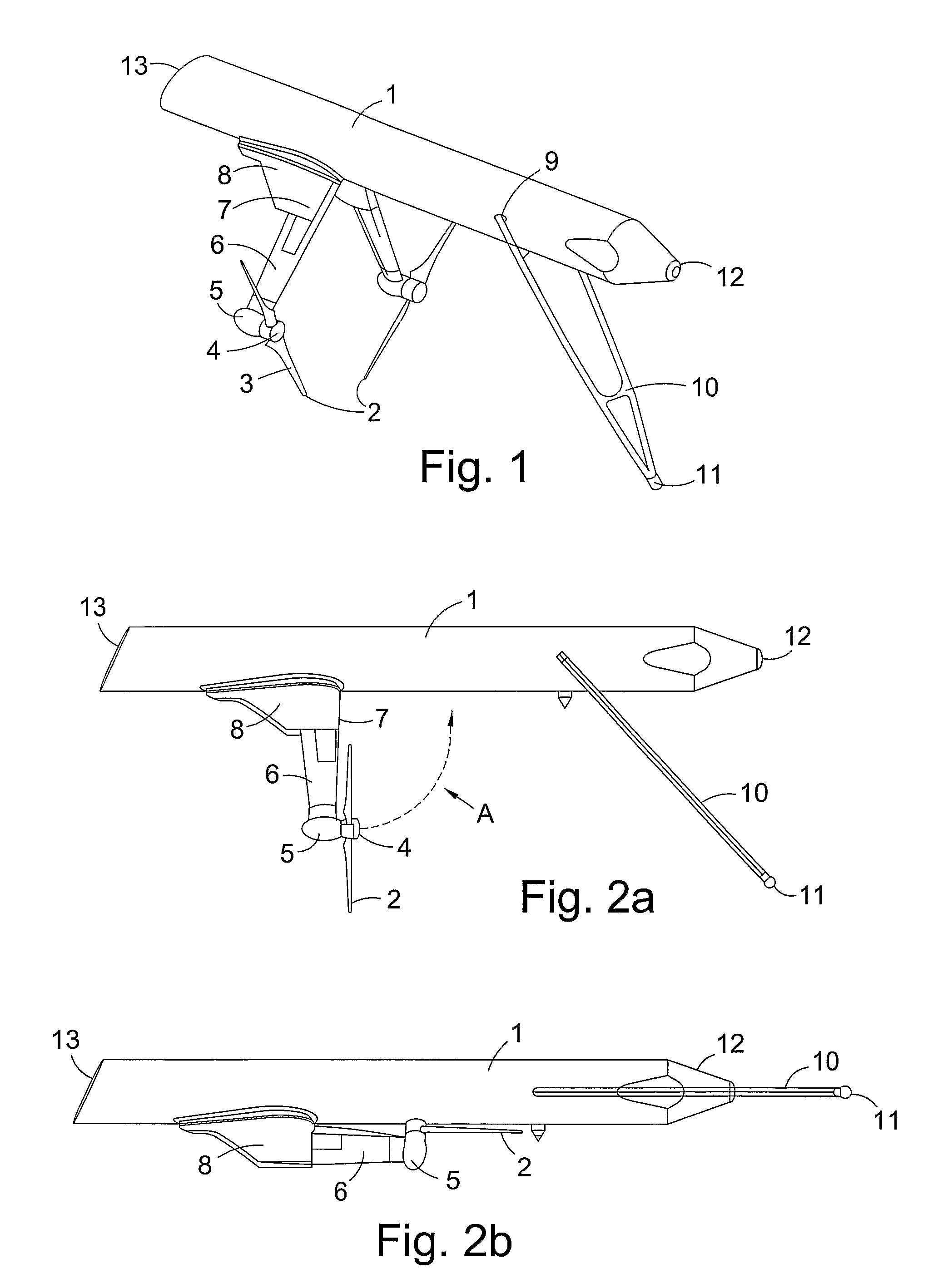
[0008]Thus with a power generating apparatus according to the present invention the realisation of a simple yet effective means of generating power in tidal locations can be realised. Preferably said rotor blades are connected through said mounting means by means of a hinged joint in a keel section of said vessel, so as to be movable from a first, or stowed position, immediately below the vessel to a second deployed condition facing the direction of tidal currents. With the rotor blades in said stowed position the present invention is advantageously significantly easier to manoeuvre and handle as the elongate cylindrical nature of the vessel allows for the vessel to be “rolled over” so as to permit maintenance of the rotor blades / power generating device without the need for large and expensive barges / cranes. Moreover the ability to stow the rotor blades immediately under the vessel means that the whole apparatus can be readily towed into harbours for maintenance as described above.
[0009]The generally cylindrical (in cross section) shape of the vessel is an essential feature of the present invention for a number of reasons, including the fact that a cylindrical vessel is inherently extremely strong and has substantial structural integrity thereby giving improved “survivability” in adverse weather conditions. Moreover the cylindrical vessel means that wave loading and water resistance (drag) is minimised. This again provides for improved survivability.
[0010]Preferably there are two rotor blades which, in said stowed or retracted position, may be arranged so as to be parallel with the longitudinal axis of the vessel. This arrangement further facilitates the handling, particularly the towing of the apparatus.
[0014]The apparatus is provided with means, for example mooring means formed and arranged for securing the apparatus to the seabed or other fixed point. Desirably the mooring configuration, preferably a yolk arrangement, allow for remote “quick” release and connection.

Problems solved by technology

Wave powered generating apparatus has proved difficult to realise effectively for a variety of reasons, not least the generally large costs associated with equipment required to withstand the power of extreme waves that occur during storms.
All of the prior art apparatus known to the inventor suffer from a number of inherent problems, including large and sophisticated designs which do not lend themselves to simple manufacturing techniques and which are prone to damage i.e. they have poor survivability in the sea; and / or are difficult to maintain / repair without the need for expensive handling or installation equipment; and / or required to be “piled” into the seabed.

Method used


Image

  • Water current powered generating apparatus
  • Water current powered generating apparatus

Examples


Embodiment Construction

[0022]An apparatus for extracting power from tidal energy is shown in FIGS. 1, 2a and 2b. The apparatus comprises a cylindrical buoyancy tube 1 which has depending from its underside dual counter-rotating rotors 2 which are driven by rotor blades 3 which rotate, about a rotor hub 4, by the action of tidal water (not shown) passing across the rotor blades 3.

[0023]In more detail the cylindrical buoyancy tube 1 comprises a hollow main section, consisting of a multi-celled structure constructed from steel plate (or reinforced concrete), with a streamlined front section 12 and a sloped rear section 13 bonded to form one unit. The cylindrical buoyancy tube 1 may contain components such as transformers and possibly power conversion equipment (not shown). Access to within the body 1 is achieved utilising watertight hatches (not shown).

[0024]Hydrodynamic support keel sections 8 are attached to the cylindrical buoyancy tube 1, providing, if required, variable longitudinal-positioning of the l...


PUM


Abstract

A power generating apparatus suitable for use in extracting energy from the movement of water, in particular tidal movement, is disclosed. The apparatus includes an elongate, generally circular in cross section, buoyancy vessel (1), having depending from its underside on a mounting means, rotatable rotor blades (2). The rotor blades are connected to a power generating means whereby in use of the apparatus movement of water across the rotor blasé, drives them so as to generate power in the power generating means.

Description

TECHNICAL FIELD OF THE INVENTION[0001]The present invention relates to a power generating apparatus for use in extracting energy from the movement of water, particularly tidal movement or other water currents, such as rivers. The invention is particularly directed to a floating apparatus.BACKGROUND OF THE INVENTION[0002]In recent years there has been a move towards so called renewable energy sources, such as wind and wave power, but wind turbines have a very high visual impact and are, of course, dependent on there being wind. Wave powered generating apparatus has proved difficult to realise effectively for a variety of reasons, not least the generally large costs associated with equipment required to withstand the power of extreme waves that occur during storms.[0003]Tidal energy, on the other hand, is based on a guaranteed energy source, that of the movement of the tides. A great number of tidal powered generating apparatus have been proposed over the years including, for example,...

Claims


Application Information

Patent Timeline
Patent Type & Authority Patents(United States)
IPC IPC(8): F03B13/26F03B13/22F03B17/06
CPCF03B13/264F03B17/061F05B2240/93Y02E10/28Y02E10/38Y02E10/30F03B13/22F03B17/06Y02E10/20
Inventor JOHNSTON, BARRY
Owner SCOTRENEWABLES MARINE POWER
Learn More