Liquid ejecting apparatus

a liquid ejection and apparatus technology, applied in printing and other directions, can solve the problems of ink jet printers, likely to generate gas bubbles, reverse effect of liquid ejection,

Active Publication Date: 2016-01-07
SEIKO EPSON CORP
View PDF1 Cites 10 Cited by
  • Summary
  • Abstract
  • Description
  • Claims
  • Application Information

AI Technical Summary

Benefits of technology

[0025]According to the configuration, Due to the provision of the bypass path, it is possible to form a circulation path through which the liquid can be circulated without passing through the pressure adjusting valve.

Problems solved by technology

Further, in the case of such a printer, gas bubbles are likely to be generated in the internal portion of the pressure chamber of the pressure adjusting valve.
However, in a case where the ink mixed with the gas bubbles (fluid) is discharged from the internal portion of the pressure chamber through the liquid ejecting head, the gas bubbles in the internal portion of the liquid ejecting head remain, and thus there is a problem in that a reverse effect is exerted to the ejection of the liquid.
Further, such a problem occurs in not only the ink jet type printer, but also commonly occurs in a liquid ejecting apparatus in which a pressure adjusting valve is disposed in a supplying path through which liquid is supplied to the liquid ejecting section.
In a case where the fluid in the internal portion of the pressure chamber is discharged through the discharging path, there is a problem in that the pressure in the internal portion of the pressure chamber decreases and air is likely to be suctioned from the nozzle.

Method used


Image

  • Liquid ejecting apparatus
  • Liquid ejecting apparatus
  • Liquid ejecting apparatus

Examples


first embodiment

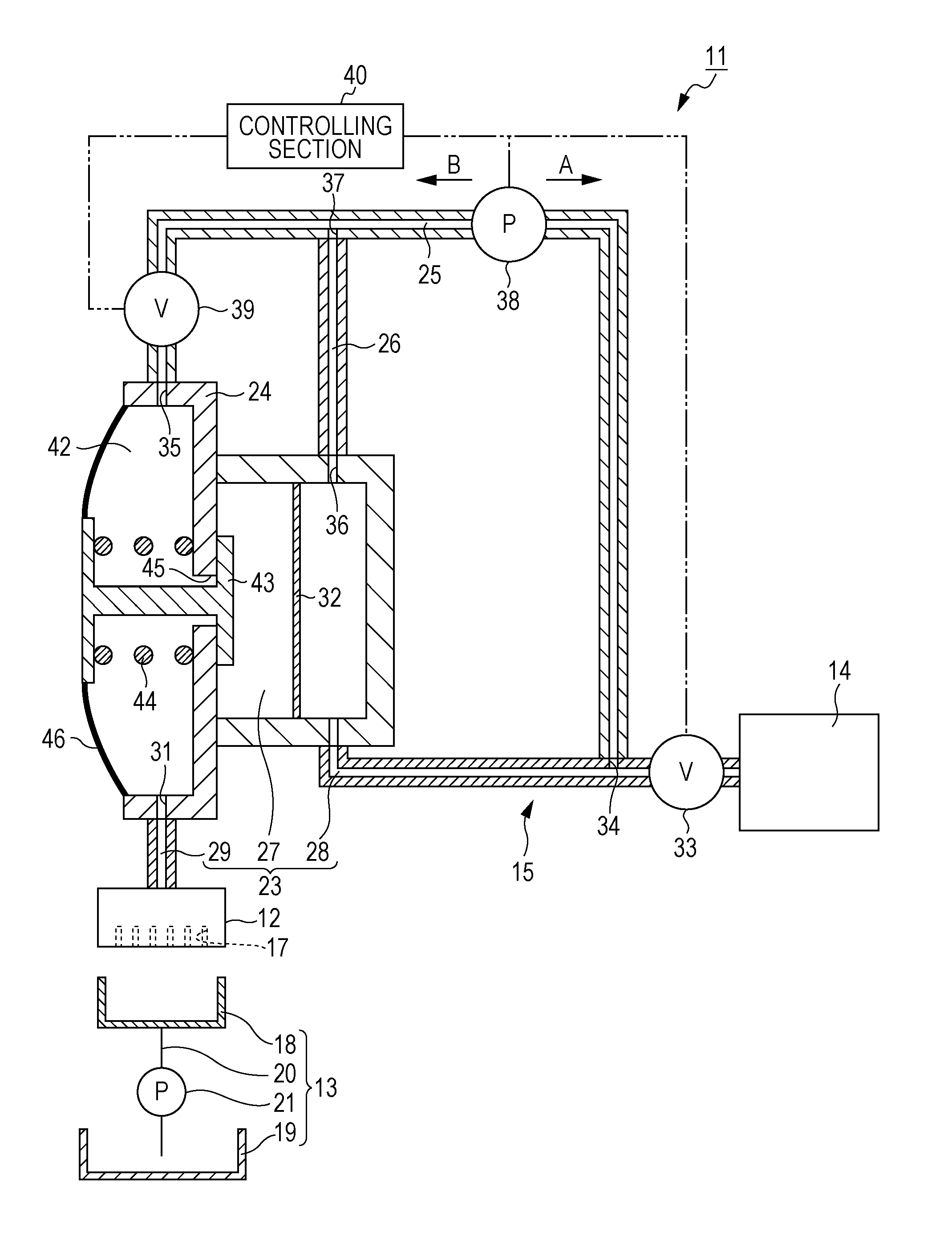
[0036]As shown in FIG. 1, the liquid ejecting apparatus 11 of the embodiment includes a liquid ejecting section 12 that ejects a liquid, a maintenance mechanism 13 that performs a maintenance of the liquid ejecting section 12, and a supplying mechanism 15 that is capable of supplying the liquid to the liquid ejecting section 12 from a liquid accommodating section 14 that accommodates the liquid. The liquid accommodating section 14 is detachably provided in the supplying mechanism 15, and the liquid accommodated in the liquid accommodating section 14 is pressurized so that the pressurized liquid can be supplied to the supplying mechanism 15.

[0037]The liquid ejecting section 12 includes at least one nozzle 17 (plural nozzles in the embodiment) in the nozzle forming surface. Further, the liquid supplied from the liquid accommodating section 14 is ejected from the nozzle 17 in the form of droplets.

[0038]The maintenance mechanism 13 includes a cap 18 that is capable of moving relative to...

second embodiment

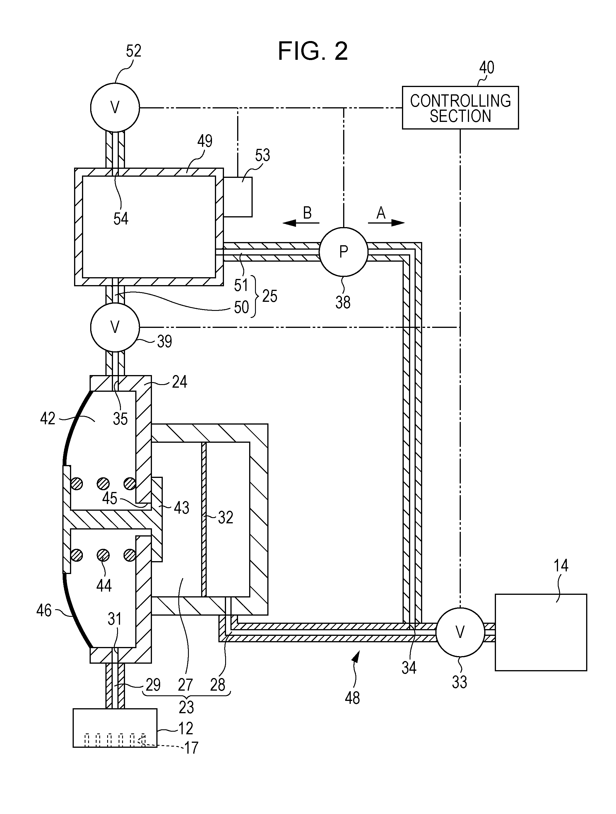
[0076]Hereinafter, the second embodiment of the liquid ejecting apparatus will be described with reference to the drawings. Further, the second embodiment is different from the first embodiment in the configuration of the supplying mechanism 48. Further, since the second embodiment is the same as the first embodiment in other respects, like elements are designated by like numbers and the descriptions thereof will not be repeated.

[0077]As shown in FIG. 2, the supplying mechanism 48 includes the fluid storage section 49 provided between the switching valve 39 and the fluid flowing mechanism 38 in the discharging path 25. In other words, the discharging path 25 is configured to include a switching valve side discharging path 50 in which the switching valve 39 is provided close to the pressure adjusting valve 24 when compared with the case of the fluid storage section 49, and a fluid flowing mechanism side discharging path 51 in which the fluid flowing mechanism 38 is provided close to ...

third embodiment

[0086]Hereinafter, the third embodiment of the liquid ejecting apparatus will be described with reference to the drawings. Further, the third embodiment is different from the first embodiment and the second embodiment in the configuration of the supplying mechanism 56. Further, since the third embodiment is substantially the same as the first embodiment and the second embodiment in other respects, like elements are designated by like numbers and the descriptions thereof will not be repeated.

[0087]As shown in FIG. 3, the discharging path 57 is configured to include an adjusting valve side discharging path 58 that connects the pressure adjusting valve 24 and the fluid storage section 49 with each other, a switching valve side discharging path 59 that connects the fluid storage section 49 and the switching valve 39 with each other, and a fluid flowing mechanism side discharging path 60 with which the fluid flowing mechanism 38 is provided. Further, the adjusting valve side discharging ...


PUM


Abstract

A liquid ejecting apparatus includes a liquid ejecting section that includes a nozzle that ejects a liquid; a supplying path that is capable of supplying the liquid accommodated in a liquid accommodating section to the liquid ejecting section; a pressure adjusting valve that is disposed in the supplying path, and includes a pressure chamber which is capable of storing the liquid, the pressure chamber being is provided with an outlet that draws out the stored liquid to the liquid ejecting section, and when a pressure in the internal portion of the pressure chamber decrease, the pressure adjusting valve being opened to adjust a pressure of the liquid supplied to the liquid ejecting section; a discharging path that connects to a communicating port which communicates with the pressure chamber in a separate position different from a position of the outlet; and a switching valve that is provided in the discharging path.

Description

BACKGROUND[0001]1. Technical Field[0002]The present invention relates to, for example, a liquid ejecting apparatus of an ink jet type printer and the like.[0003]2. Related Art[0004]As an example of the liquid ejecting apparatus of a related art, there is an ink jet type printer in which ink (liquid) that is supplied from a liquid storage section (a liquid accommodating section) is ejected to media from a liquid ejecting section to thereby perform printing. Further, among these types printers, there is a printer in which a pressure adjusting valve called a self-sealing valve is provided in the midway of a supplying path through which ink is supplied from the liquid storage section to the liquid ejecting section (For example, JP-A-2011-255643).[0005]The pressure adjusting valve includes a pressure chamber that causes the ink to stay. When the ink is consumed in a liquid ejecting head (a liquid ejecting section) and thus a pressure of the ink in the internal portion of the pressure cha...

Claims


Application Information

Patent Timeline
Patent Type & Authority Applications(United States)
IPC IPC(8): B41J2/175
CPCB41J2/17596B41J2/175
Inventor KAMEI, HIROYUKIKIMURA, HITOTOSHI
Owner SEIKO EPSON CORP
Why Eureka
Try Eureka