
Method for forming a parallel processing system

a parallel processing and system technology, applied in the direction of program control, multi-processing architecture, instruments, etc., can solve the problem that the algorithm will not be executed as intended, and achieve the effect of suppressing the wiring for connecting the elements used to arrange the circuit and designing even more flexibly

Active Publication Date: 2011-08-11
FUJIFILM BUSINESS INNOVATION CORP
View PDF14 Cites 6 Cited by
  • Summary
  • Abstract
  • Description
  • Claims
  • Application Information

AI Technical Summary

Benefits of technology

Enables the efficient design and simulation of parallel processing systems by allowing the description of parallel processes with unambiguous variable handling and data latency synchronization, effectively utilizing multiple parallel elements for high-speed execution without specific hardware knowledge.

Problems solved by technology

However, in parallel descriptions with variables, if the course or history of variables is not unambiguously determined, there is the possibility that the algorithm will not be executed as intended.

Method used


Image

  • Method for forming a parallel processing system
  • Method for forming a parallel processing system
  • Method for forming a parallel processing system

Examples


Embodiment Construction

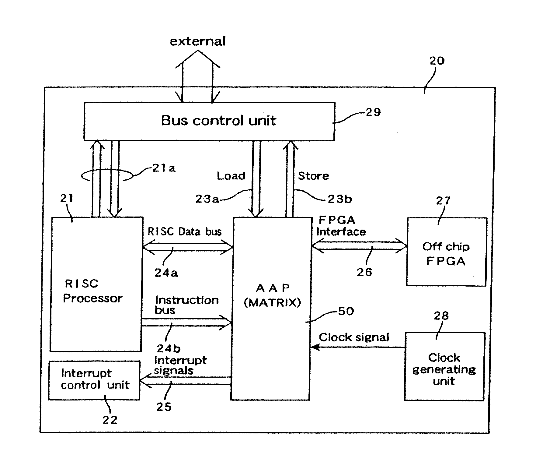
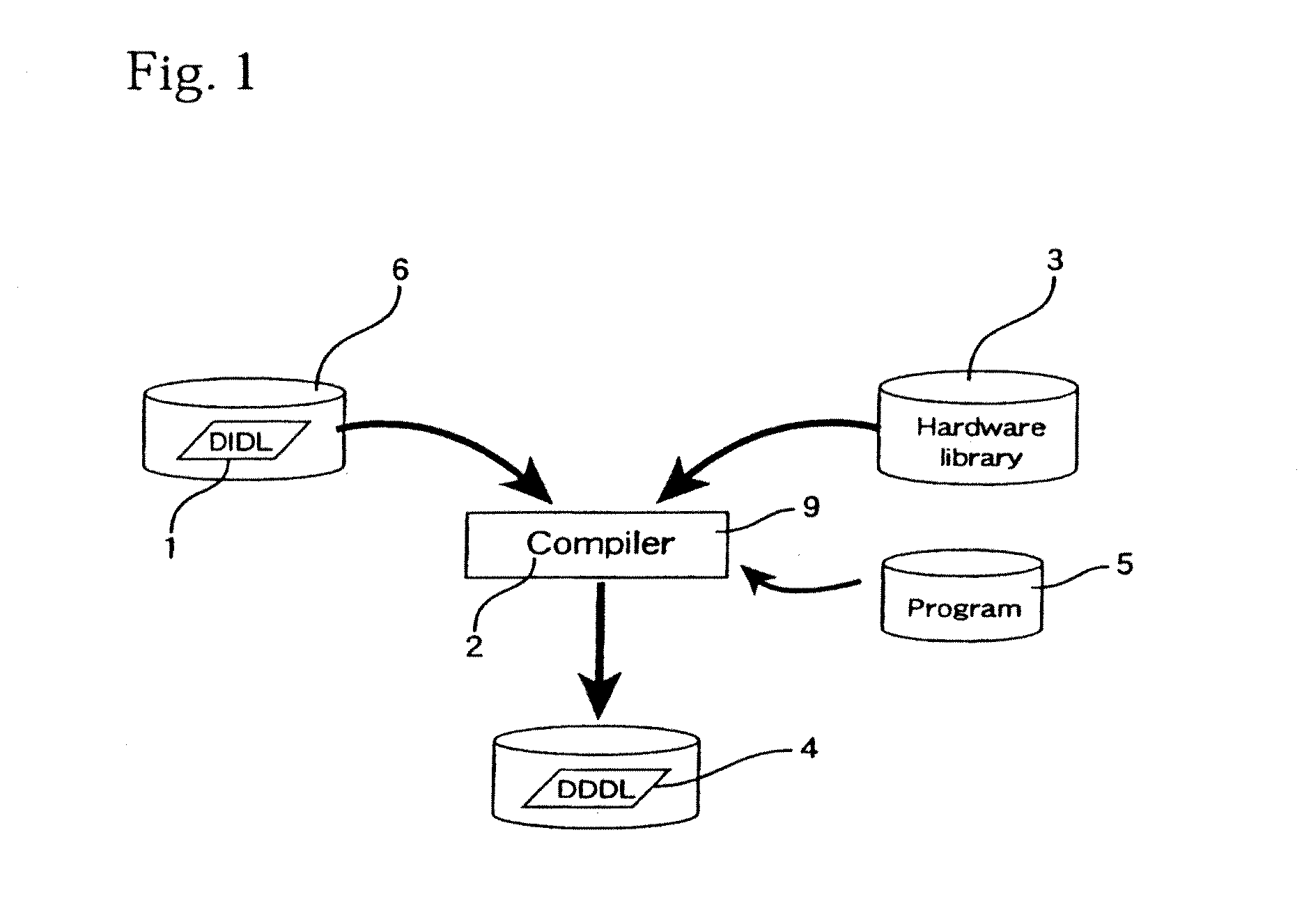
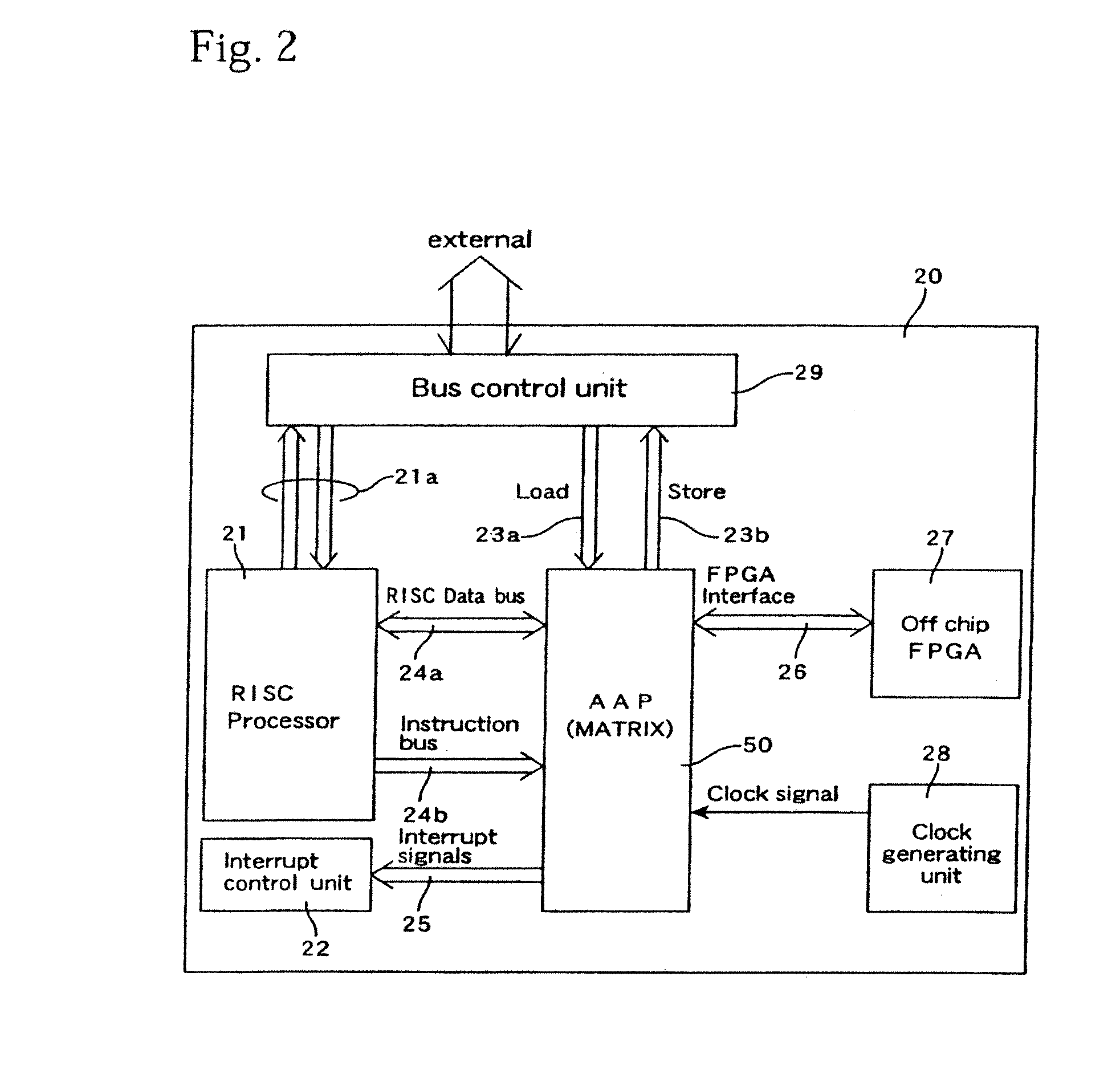
[0040]FIG. 1 shows an outline of procedure for designing hardware using a definition file included in the present invention. A definition file 1 is called DIDL (Device Independent Description Language), and is converted by a compiler 2, which refers to information in a hardware library 3, to hardware configuration information 4 that uses the hardware information stored in the library 3. The hardware configuration information 4 is called DDDL (Device Dependent Description Language). The compiler 2 is realized using a general-purpose computer 9 equipped with suitable hardware resources and functions as a compiler by installing a program 5 for parallel system designing that interprets the DIDL 1 and generates the DDDL 4. The DIDL 1 is provided by storing on a computer-readable recording medium 6, such as a CD-ROM or a magnetic disk. The DIDL 1 is also provided via communication such as a computer network like the Internet, with the provided DIDL 1 being used having been recorded on a s...


PUM


Abstract

A definition file included in the present invention includes a plurality of parallel descriptions that respectively define a plurality of parallel processes performed independently. The plurality of parallel descriptions include a first parallel description showing a first parallel process with a plurality of data inputs including at least one data input into which output data of another parallel process is inputted, with data with the same latency from input in a parallel processing system are inputted into the plurality of data inputs. A forming method includes a first step of generating, based on a hardware library in which information on a plurality of types of elements is stored, hardware configuration information including circuit configurations for executing the parallel processes that include at least one of the plurality of types of elements; and a second step of adding a delay element to the hardware configuration information so that data with a same latency from input into the parallel processing system are inputted into the plurality of data inputs of the circuit configuration for executing the first parallel process, and therefore the hardware configuration information is generated by this method.

Description

TECHNICAL FIELD[0001]The present invention relates to designing a parallel processing system and in particular to a method and apparatus that generate hardware configuration information for a parallel processing system based on a definition file and to a method of simulating a parallel processing system based on a definition file.BACKGROUND ART[0002]A number of types of languages are used when designing LSIs and ASICs. High-level languages such as “C” that have a high degree of abstraction are languages on a procedural level and are suited to showing how an entire process is executed in order on an instruction-by-instruction basis. Description on this level normally has no hardware dependency, is composed of application programs that can be received by a suitable computer, and is normally used to describe the specification of an LSI or an entire process executed by an LSI. Hardware description languages (HDL) such as Verilog-HDL or VHDL are also referred to as RTL and are used to de...

Claims


Application Information

Patent Timeline
Patent Type & Authority Applications(United States)
IPC IPC(8): G06F15/76G06F9/06G06F11/25G06F17/50G06F15/16G06F15/80
CPCG06F17/5045G06F30/30
Inventor HIROSHI, SHIMURA
Owner FUJIFILM BUSINESS INNOVATION CORP
Learn More