Stationary Induction Apparatus

Inactive Publication Date: 2016-05-12
HITACHI LTD
View PDF4 Cites 4 Cited by
  • Summary
  • Abstract
  • Description
  • Claims
  • Application Information

AI Technical Summary

Benefits of technology

[0015]According to the present invention, it is possible to sufficiently decrease the noise and prevent rainwater and dust from ent

Problems solved by technology

This electromagnetic vibration, due to its insulating material having a substantially non-compressible cha

Method used


Image

  • Stationary Induction Apparatus
  • Stationary Induction Apparatus
  • Stationary Induction Apparatus

Examples


Example

First Exemplary Embodiment

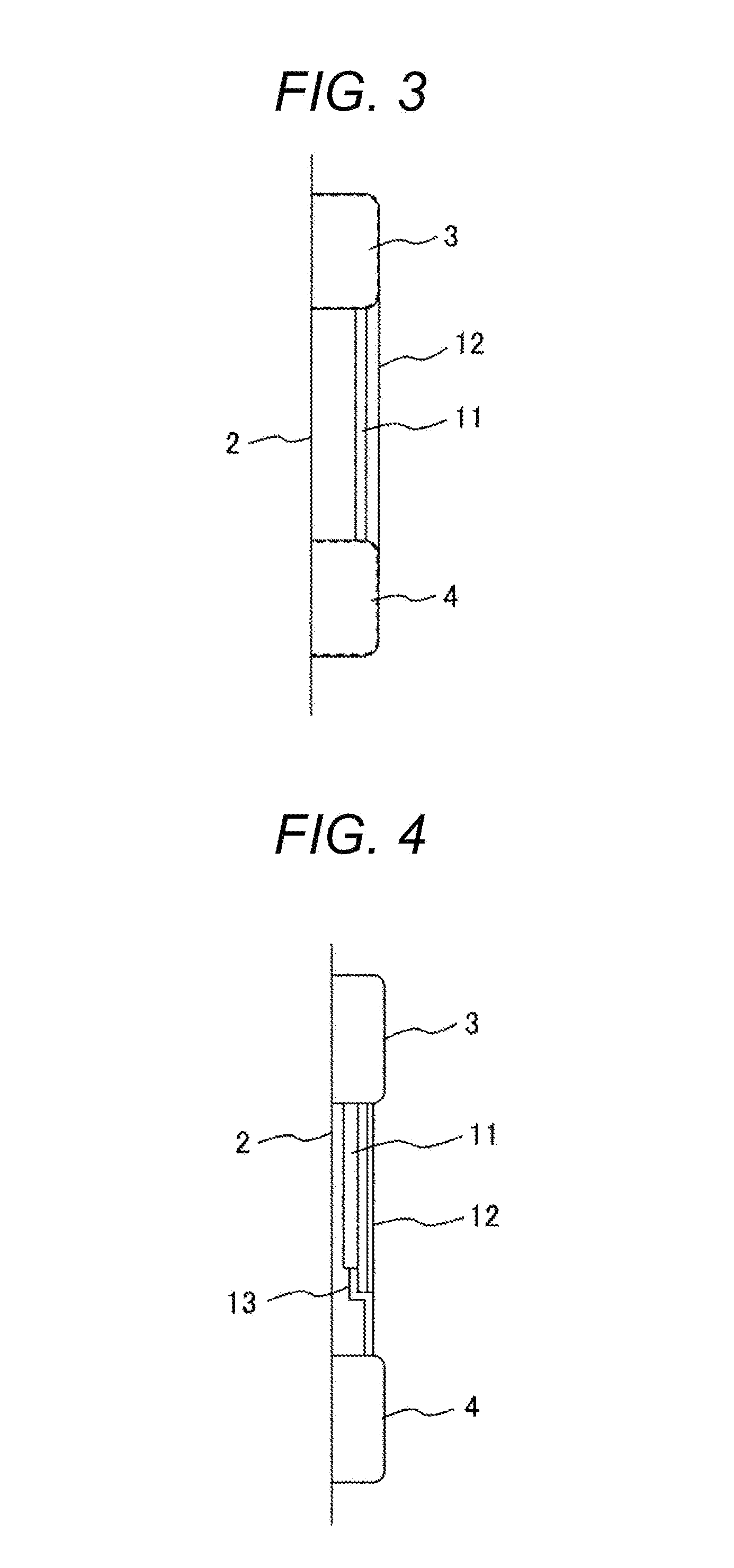
[0030]FIG. 3 illustrates a transformer as a first exemplary embodiment of a stationary induction apparatus of the present invention and illustrates a detailed mounting state of a sound insulating board mounted to a tank of the transformer.

[0031]In the present embodiment, as illustrated in FIG. 3, a sound insulating board 11 is partially weld-joined (spotwise) at each of both ends, with each of upper and lower stays 3 and 4. In addition, a sealing material 12 made of iron is provided at an outer periphery of a welded portion. The sealing material 12 is provided so as to include the outer periphery of the welded portion and to cover an outer surface whole periphery of the sound insulating board 11. Moreover, the sealing material 12 is entirely weld-joined (whole-periphery welding), at each of both ends, with each of the upper and lower stays 3 and 4.

[0032]In other words, in the present exemplary embodiment illustrated in FIG. 3, installation is performed such...

Example

Second Exemplary Embodiment

[0034]FIG. 4 illustrates a transformer that is a second exemplary embodiment of the stationary induction apparatus of the present invention and illustrates a detailed mounting state of the sound insulating board mounted to the tank of the transformer.

[0035]In the present exemplary embodiment, as illustrated in FIG. 4, an upper end of the sound insulating board 11 is partially joined (spotwise) with an upper end stay 3 and a lower end of the sound insulating board 11 is partially weld-joined (spotwise) to a connecting member 13. The connecting member 13 is entirely weld-joined (whole-periphery welding) with a lower end stay 4, and the sealing material 12 made of iron is provided on an outer periphery of a welded portion of the sound insulating board 11. Furthermore, the sealing material 12 is provided so as to include the outer periphery of the welded portion and to cover an outer surface whole periphery of the sound insulating board 11. In addition, an upp...

Example

Third Embodiment

[0038]FIG. 5 illustrates a transformer that is a third exemplary embodiment of the stationary induction apparatus of the present invention and illustrates a detailed mounting state of the sound insulating board mounted to the tank of the transformer.

[0039]In the present exemplary embodiment, as illustrated in FIG. 5, a lower end of the sound insulating hoard 11 is partially joined (spotwise) with the lower end stay 4 and an upper end of the sound insulating board 11 is partially weld-joined (spotwise) with a connecting member 13. The connecting member 13 is entirely weld-joined (whole-periphery welding) with the upper end stay 3, and the sealing material 12 made of iron is provided on an outer surface whole periphery of a welded portion of the sound insulating board 11. Furthermore, the sealing material 12 is provided so as to include the outer periphery of the welded portion and to cover the outer surface whole periphery of the sound insulating board 11. In addition...


PUM


Abstract

Provided is a stationary induction apparatus capable of sufficiently decreasing noise and preventing rainwater and dust from entering between welded portions even when using a method of mounting a sound insulating board between an upper stay and a lower stay. The stationary induction apparatus of the present invention includes a stationary induction apparatus main body, a tank, an upper stay and a lower stay, and a sound insulating board. The tank houses the stationary induction apparatus main body and an insulating material. Each of the upper stay and the lower stay is provided respectively, at least at each of an upper portion and a lower portion of an outer surface of the tank. The sound insulating board is disposed between the upper stay and the lower stay. The sound insulating board is partially weld-joined, at each of both ends, with a supporting member, and a sealing material is provided at an outer periphery of a welded portion of the sound insulating board.

Description

TECHNICAL FIELD[0001]The present invention relates to a stationary induction apparatus, particularly relates to the stationary induction apparatus that is suitable for a situation in which, for example, a sound insulating board is provided on an outer surface of a tank so as to reduce noise occurring from a main body of the stationary induction apparatus such as a transformer and a reactor.BACKGROUND ART[0002]In recent years, as urban areas are expanding, more and more residential areas are built in proximity to a substation, or the like. Along with this trend, noise-reduction requirements for a stationary induction apparatus including a transformer and a reactor are becoming more stringent.[0003]Noise due to the stationary induction apparatus is classified into the noise occurring in a core of the stationary induction apparatus main body and the noise occurring in auxiliaries such as an air blower and an oil transfer pump of a cooler. Among the noise, electromagnetic vibration due ...

Claims


Application Information

Patent Timeline
IPC IPC(8): H01F27/33H01F27/02
CPCH01F27/02H01F27/33
Inventor SUGIYAMA, SHOYAMAGISHI, AKIRAHIROBE, RYOJIOYAMA, TAKU
Owner HITACHI LTD
Why Eureka
Try Eureka